Home/
Registry/
Ford/
Bronco/
1966-1977/
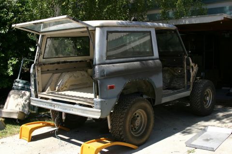
1974 Ford Bronco/
Photo
supermotors.net/registry/media/307404
Ford Bronco 4WD Transfer Case Disassembly Procedure - Shop Manual Page 6-21
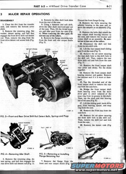
Service procedure page detailing 4-wheel drive transfer case major repair disassembly steps with labeled photographs.
This is page 6-21 from a Ford shop manual, Part 6-3 covering the 4-Wheel Drive Transfer Case, section 3 'Major Repair Operations.' It presents the step-by-step DISASSEMBLY procedure (steps 1-20) for the transfer case, including cleaning the case, removing the retaining plugs, detent springs and balls for the front and rear drive shift rail detent rods, removing the idler shaft lock plate and idler shaft (with a caution not to lose the rollers), removing the flange retaining nuts and flanges from the front and rear output shafts, removing the adapter housing, rear output shaft bearing retainer, shift rails and forks, front output shaft rear cover and shims, bearing retainer and gasket, bearings, cups, sliding gear, main drive gear, and detent rods. Four figures are included: Fig. 3 shows the front and rear drive shift rail detent balls, springs and plugs on the case; Fig. 4 shows removing the idler shaft (thrust washers, shaft, idler gear labeled); Fig. 5 shows removing or installing the flange retaining nut using Tool 4851-K; and Fig. 6 shows removing the flange with Tool T56L-4851-C. Figure reference codes C 1601-A through C 1604-A appear on the illustrations.
Is this accurate? Sign in to help verify it.
Frequently asked questions
- What tool is used to remove or install the transfer case flange retaining nut?
- Fig. 5 shows the flange retaining nut being removed or installed using Tool 4851-K.
- What tool removes the output shaft flange on this transfer case?
- Fig. 6 shows the flange being removed with Tool T56L-4851-C.
- What caution is given when removing the idler gear?
- When removing the idler gear, do not lose any of the rollers. A similar caution applies when removing the rear output shaft bearing retainer and output shaft assembly.
- What happens to the front flange O-ring during disassembly?
- The document states to discard the front flange O-ring.
- How is the front output shaft removed from the case?
- Wedge the front output shaft front bearing away from the main drive gear to allow removal of the snap ring from its groove in the shaft, then tap the shaft and rear bearing out of the case (Fig. 8).
Comments
More from this build

No comments yet.