Home/
Registry/
Ford/
Bronco/
1966-1977/
1974 Ford Bronco/
Photo
supermotors.net/registry/media/307409
Ford Bronco 4WD Transfer Case Exploded Diagram - Shift Rails & Output Shaft

Reference · 1966-1977 BroncoAll 140 exploded parts diagrams
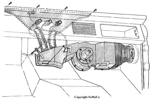
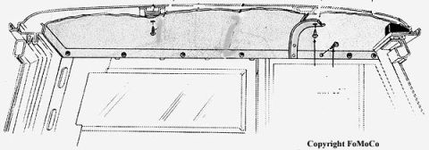
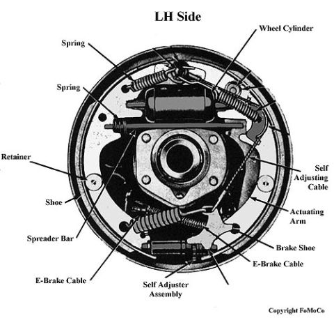
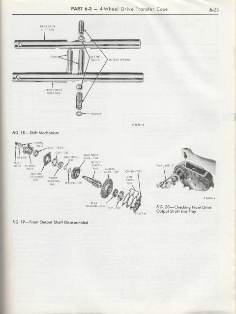
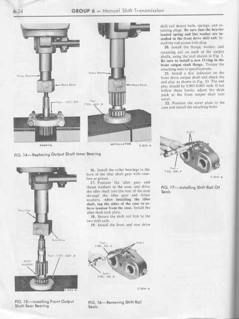
Exploded parts diagrams of the transfer case shift mechanism and front output shaft showing bearings, gears, and detent components.
Part of 1966-1977 Ford Bronco Exploded Parts Diagrams
This is page 6-25 from a Ford shop manual, Part 6-3 covering the 4-Wheel Drive Transfer Case. The page contains three figures. Fig. 18 shows the shift mechanism in exploded view, labeling the rear drive shift rail, front drive shift rail, rods, detent balls, detent springs, and washer. Fig. 19 is an exploded parts diagram of the front output shaft, identifying components with Ford basic part numbers: O-ring and seal (7B215), cup (1202), snap ring (7026), main drive gear (7100), output shaft (7061), sliding gear (7100), cover (7085), shim pack (7029), nut (351126), flange (7B214), bearing retainer (7085), front bearing (7065), spacer (7067), rear bearing (1216), and cup (7169). Fig. 20 is a photograph demonstrating how to check front drive output shaft end play using a dial indicator with Tool 4201-C. Figure reference codes C 1616-A, C 1617-A, and C 1618-A appear on the page. A reader can learn the assembly order and part identification for the transfer case shift rails and front output shaft, plus the setup for measuring output shaft end play. The rest of the visible text is bleed-through from the reverse page and is not readable.
Is this accurate? Sign in to help verify it.
Frequently asked questions
- What part number is the front output shaft in the Ford transfer case?
- The output shaft is labeled part number 7061 in Fig. 19, Front Output Shaft Disassembled.
- What components make up the transfer case shift mechanism?
- Fig. 18 shows the rear drive shift rail, front drive shift rail, rods, detent balls, detent springs, and a washer.
- How is front drive output shaft end play checked?
- Fig. 20 shows checking front drive output shaft end play using a dial indicator with Tool 4201-C mounted on the transfer case.
- What bearings are used on the front output shaft?
- Fig. 19 shows a front bearing (7065) with cup (1202) and a rear bearing (1216) with cup (7169), plus a bearing retainer (7085).
- What holds the flange on the front output shaft?
- Per Fig. 19, the flange (7B214) is retained by a washer and nut (351126).
No comments yet.