Home/
Registry/
Ford/
Bronco/
1966-1977/
1974 Ford Bronco/
Photo
supermotors.net/registry/media/307972
1974 Ford Bronco Drum Brake Diagram - LH Side Parts & Self Adjuster Layout

Reference · 1966-1977 BroncoAll 140 exploded parts diagrams
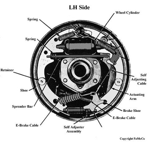

Drum brake assembly diagram identifying shoes, springs, wheel cylinder, self-adjuster, and parking brake cables on the left side.
Part of 1966-1977 Ford Bronco Exploded Parts Diagrams
This document is a labeled photographic diagram (Ford Motor Company copyright) showing the left-hand (LH) side drum brake assembly with the drum removed. Uploaded to a 1974 Ford Bronco gallery, it identifies the major components of a self-adjusting drum brake as installed on the vehicle. Callouts point to the wheel cylinder at the top, two return springs, the shoe retainer, the brake shoes, the spreader bar between the shoes, the self-adjusting cable running down the trailing side, the actuating arm it connects to, the self-adjuster assembly at the bottom, and the emergency (parking) brake cable attachments. A reader can use this diagram to identify parts during drum brake inspection, disassembly, or reassembly, particularly to confirm correct routing of the self-adjusting cable to the actuating arm and correct placement of springs, retainer, spreader bar, and e-brake cable on the left side of the vehicle. No part numbers, torque specifications, or year/model applicability statements appear on the document itself; the only text present is the component labels, the 'LH Side' heading, and the FoMoCo copyright notice.
Is this accurate? Sign in to help verify it.
Frequently asked questions
- What brake components are labeled in this diagram?
- The diagram labels the wheel cylinder, two springs, retainer, shoe, brake shoe, spreader bar, self adjusting cable, actuating arm, self adjuster assembly, and two e-brake cable points.
- Which side of the vehicle does this drum brake diagram show?
- It is labeled 'LH Side,' meaning the left-hand (driver's) side drum brake assembly.
- Where does the self-adjusting cable route in this drum brake?
- Per the diagram, the self adjusting cable runs down the side of the assembly to the actuating arm, which connects to the self adjuster assembly at the bottom.
- Where is the wheel cylinder located in this assembly?
- The wheel cylinder is at the top of the backing plate, between the upper ends of the two brake shoes, with springs attached nearby.
- Who produced this diagram?
- The image carries a 'Copyright FoMoCo' notice, indicating Ford Motor Company.

No comments yet.