Home/
Registry/
Ford/
Bronco/
1966-1977/
1974 Ford Bronco/
Photo
supermotors.net/registry/media/307977
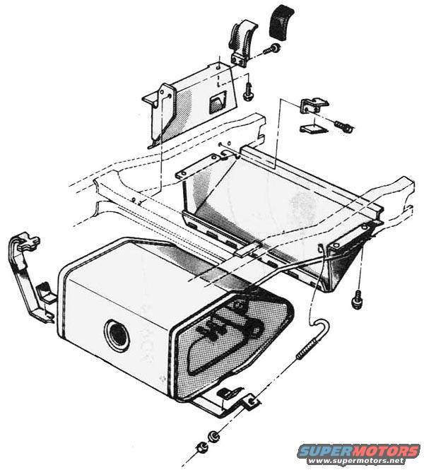
1974 Ford Bronco Gas Tank Exploded Diagram - Fuel Tank Mounting & Straps
Reference · 1966-1977 BroncoAll 140 exploded parts diagrams
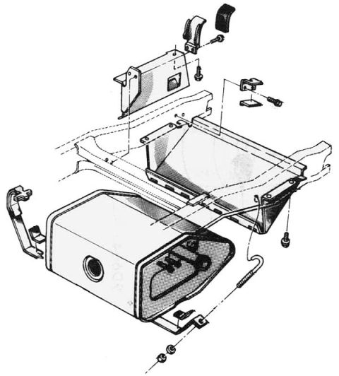
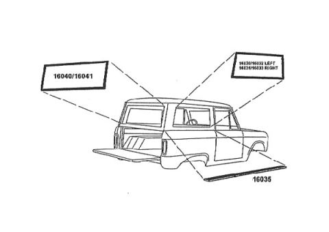
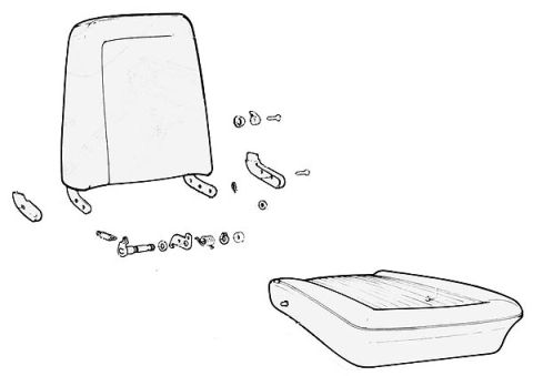
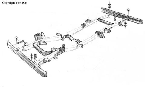
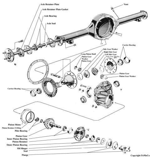
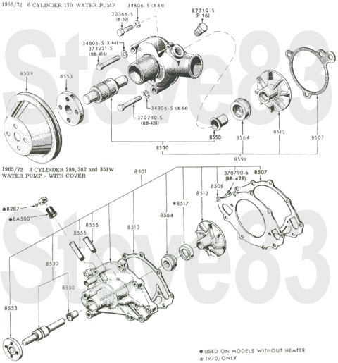
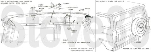
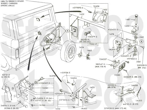
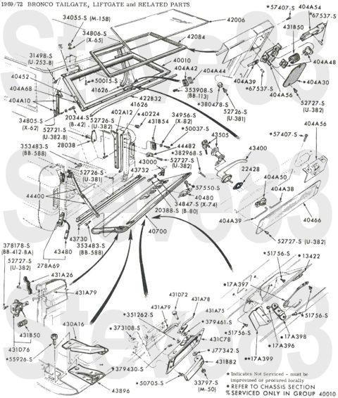

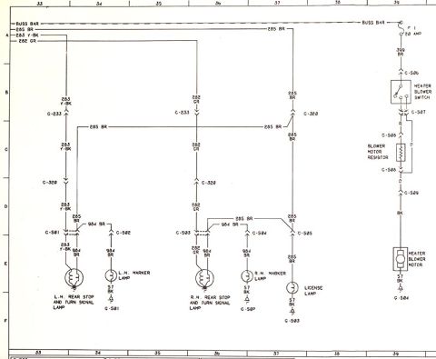
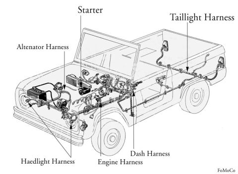
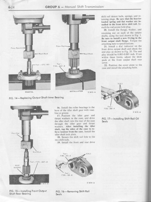

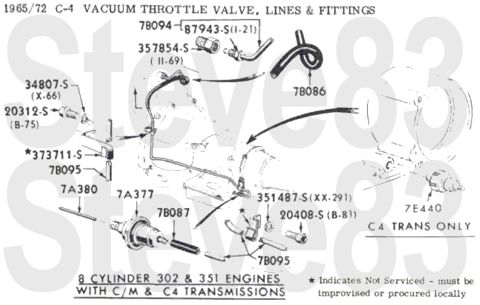
Exploded parts diagram of a fuel tank assembly with mounting straps, brackets and hardware.
Part of 1966-1977 Ford Bronco Exploded Parts Diagrams
This document is an exploded-view parts illustration showing the fuel (gas) tank assembly and its mounting components, uploaded to a 1974 Ford Bronco gallery. The drawing depicts the fuel tank itself with a round filler opening on its side, tank retaining straps and hanger brackets, a protective shield or panel mounted above/behind the tank, the frame crossmember area where the tank installs, small mounting clips, bolts, screws, and washers, and a fuel or vent line with a coiled/spring-protected section connecting to the tank sender area. Dashed lines indicate the assembly relationships between fasteners, brackets, and mounting points on the frame. The image contains no legible text, part numbers, callout numbers, or legend, so it serves purely as a visual reference for how the fuel tank, straps, shield, and hardware fit together and where fasteners attach. A reader can use this diagram to understand the order of assembly and the hardware locations when removing or installing the gas tank, but must consult other documentation for part numbers, torque specifications, or year-specific details.
Is this accurate? Sign in to help verify it.
Frequently asked questions
- What does this diagram show?
- It is an exploded-view illustration of a fuel (gas) tank assembly, showing the tank, mounting straps and brackets, a shield/panel, frame mounting area, fasteners, and a fuel/vent line.
- Does the diagram list any part numbers or torque specs?
- No. The illustration contains no legible text, part numbers, callout labels, or torque values, it is a purely pictorial exploded view.
- How is the fuel tank mounted according to the diagram?
- The diagram shows the tank held by straps/brackets attached to the frame area, with a shield or panel and various bolts, screws, and clips shown in exploded relation via dashed assembly lines.
- Where is the filler opening on the tank in this diagram?
- The drawing shows a round filler opening on the side face of the tank.


No comments yet.