Home/
Registry/
Ford/
Bronco/
1966-1977/
1974 Ford Bronco/
Photo
supermotors.net/registry/media/307980
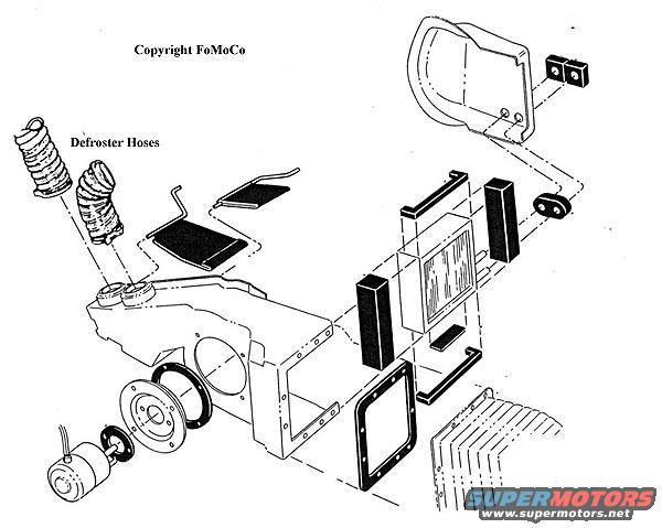
1974 Ford Bronco Heater Assembly Exploded Diagram - Defroster Hoses & Blower
Reference · 1966-1977 BroncoAll 140 exploded parts diagrams
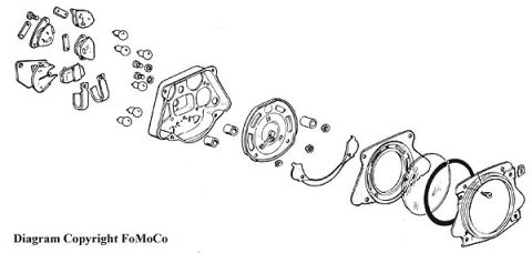
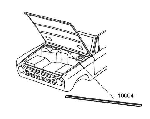
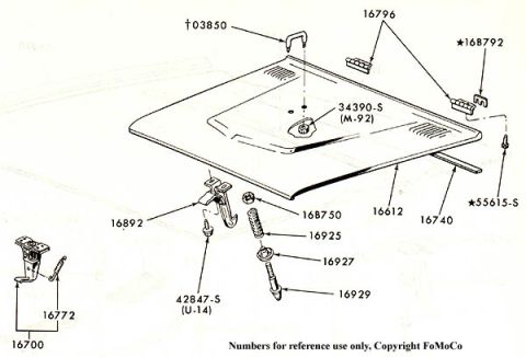
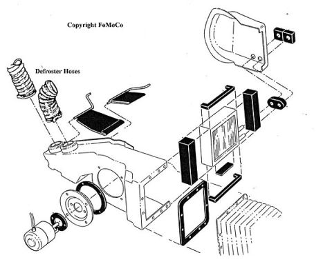
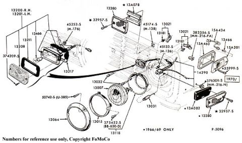
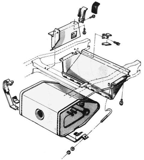
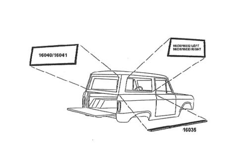
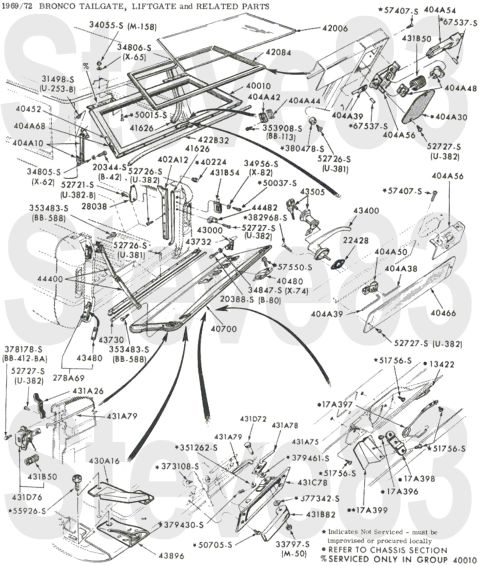
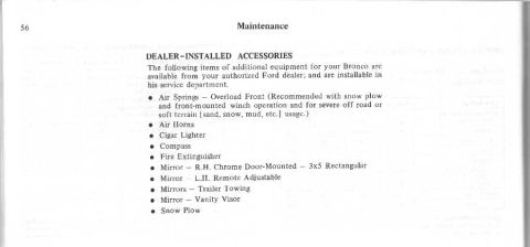
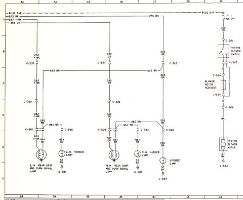
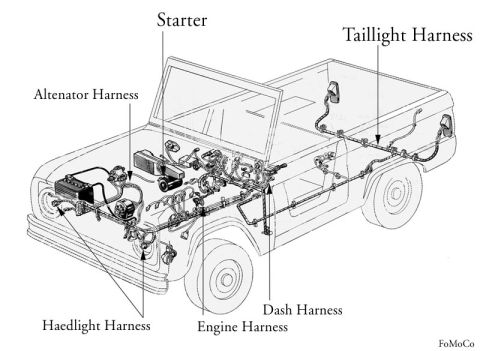
Exploded parts diagram of a heater and defroster assembly with hoses, core, blower and housing.
Part of 1966-1977 Ford Bronco Exploded Parts Diagrams
This document is an unlabeled exploded-view parts illustration (Copyright FoMoCo) of a heater and defroster assembly, uploaded to a 1974 Ford Bronco gallery as 'heater.jpg'. The only text callout identifies the 'Defroster Hoses', two flexible corrugated ducts shown at the upper left connecting to outlets on top of the heater plenum. The drawing depicts the complete heater box assembly in exploded form: the main heater housing with defroster outlets, a round blower motor with impeller/fan wheel and its mounting plate, gasket and seal rings for the blower opening, the heater core with surrounding foam sealing strips, various rectangular gaskets and seals, an access/mounting panel with attaching hardware, and the firewall or cowl area where the assembly mounts. No part numbers, torque specifications, quantities, or model-year applicability are printed on the diagram. A reader can learn the physical arrangement and assembly order of the heater components, how the blower motor, heater core, seals, and defroster hoses fit together in the housing, which is useful when disassembling or rebuilding the heater box, but must consult other sources for part numbers and fastener specs.
Is this accurate? Sign in to help verify it.
Frequently asked questions
- What components are shown in this heater diagram?
- The exploded view shows the heater housing/plenum, defroster hoses, blower motor with fan wheel, heater core, foam seal strips, gaskets, and a mounting/access panel with screws, plus the firewall/cowl area.
- Does the diagram label any parts?
- Only one label is present: 'Defroster Hoses', pointing to the two flexible corrugated hoses at the upper left. All other components are unlabeled.
- Are part numbers or torque specs included?
- No. The diagram contains no part numbers, torque values, or quantities, only the illustration, the 'Defroster Hoses' callout, and a 'Copyright FoMoCo' notice.
- Where do the defroster hoses connect?
- The diagram shows the two flexible defroster hoses attaching to round outlets on the top of the heater plenum/housing.
No comments yet.