Home/
Registry/
Ford/
Bronco/
1966-1977/
1974 Ford Bronco/
Photo
supermotors.net/registry/media/307998
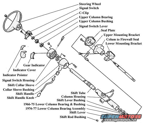
1966-77 Ford Bronco Steering Column Exploded Parts Diagram - Column Assembly
Reference · 1966-1977 BroncoAll 140 exploded parts diagrams
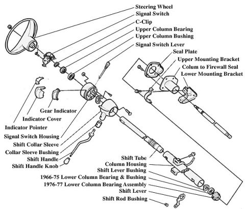
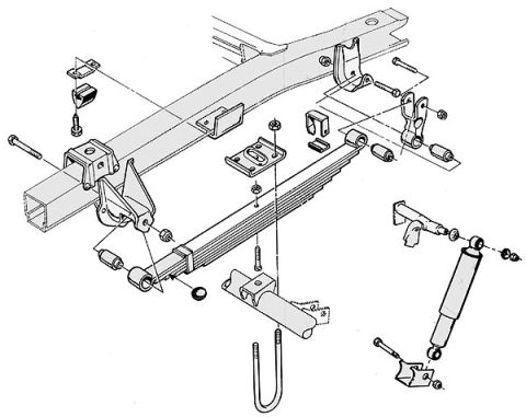
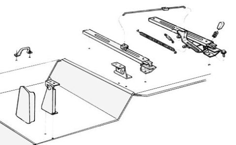
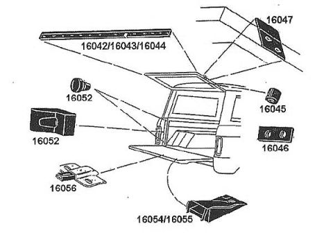
Exploded parts diagram of a steering column showing wheel, signal switch, bearings, shift tube and brackets.
Part of 1966-1977 Ford Bronco Exploded Parts Diagrams
This document is an exploded parts diagram of a steering column assembly, uploaded to a 1974 Ford Bronco gallery. The illustration shows the complete steering column broken apart into its individual components, each identified by a labeled callout line. Components shown, in order from the steering wheel end downward, include the steering wheel, signal switch, C-clip, upper column bearing and bushing, signal switch lever, gear indicator with indicator cover and pointer, signal switch housing, shift collar sleeve and collar sleeve bushing, shift handle and shift handle knob, shift tube, and column housing. Mounting hardware shown includes the seal plate, upper mounting bracket, column-to-firewall seal (labeled 'Colum to Firewall Seal'), and lower mounting bracket. At the lower end of the column, the diagram distinguishes between two lower bearing designs: a '1966-75 Lower Column Bearing & Bushing' and a '1976-77 Lower Column Bearing Assembly,' along with the shift lever, shift lever bushing, and shift rod bushing. A reader can use this diagram to identify part names, understand assembly order and relative positions of steering column components, and determine which lower column bearing style applies to a given model year. No part numbers, torque values, or textual instructions appear on the drawing.
Is this accurate? Sign in to help verify it.
Frequently asked questions
- What steering column parts are shown in this exploded diagram?
- The diagram labels the steering wheel, signal switch, C-clip, upper column bearing and bushing, signal switch lever, seal plate, upper and lower mounting brackets, column-to-firewall seal, gear indicator, indicator cover, indicator pointer, signal switch housing, shift collar sleeve, collar sleeve bushing, shift handle and knob, shift tube, column housing, shift lever bushing, lower column bearing components, shift lever, and shift rod bushing.
- Is there a difference in the lower column bearing by year?
- Yes. The diagram distinguishes a '1966-75 Lower Column Bearing & Bushing' from a '1976-77 Lower Column Bearing Assembly.'
- What holds the steering column to the vehicle?
- The diagram shows a seal plate, an upper mounting bracket, a column-to-firewall seal, and a lower mounting bracket as the mounting components.
- Does the diagram show the gear/shift indicator parts?
- Yes. It labels the gear indicator, indicator cover, and indicator pointer near the signal switch housing.
- Are any part numbers or torque specs listed?
- No. The diagram contains only component name callouts; no part numbers, torque values, or fastener specifications are shown.
No comments yet.