Home/
Registry/
Ford/
Crown Victoria/
1998-2011/
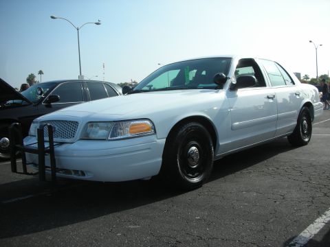
2001 Ford Crown Victoria/
Photo
supermotors.net/registry/media/528031
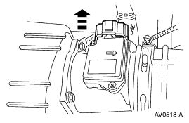
Ford Crown Victoria Mass Air Flow (MAF) Sensor Removal Diagram AV0518-A
Reference · 1998-2011 Crown VictoriaAll 18 manual pages
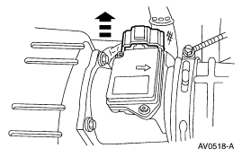


Service manual figure showing a component with directional install/remove arrows (figure AV0518-A).
Part of 1998-2011 Ford Crown Victoria Manual Pages
This document is a single black-and-white line-art illustration from a Ford service manual, identified by the Ford illustration code AV0518-A in the lower right corner. The drawing depicts a sensor or module mounted on what appears to be the air intake/air cleaner outlet tube area of an engine, with a bold upward-pointing arrow indicating the direction to lift or remove the component, and a small directional arrow marked on the component housing itself. No written instructions, part numbers, torque specifications, or captions accompany the illustration, it is purely a graphical removal/installation reference. A reader can learn the general mounting location of the depicted component and the direction in which it should be lifted during removal, but must rely on the surrounding manual text (not included in this scan) for step-by-step procedures, fastener specifications, or part identification. The illustration style and code format are consistent with Ford workshop manual figures of the late 1990s to early 2000s, matching the uploader's claimed 2001 Ford Crown Victoria, though the image itself does not state a year, model, or engine application.
Is this accurate? Sign in to help verify it.
Frequently asked questions
- What does this diagram show?
- It is a line-art service manual illustration (Ford figure code AV0518-A) showing a component mounted on the engine air intake area, with an upward arrow indicating the direction to lift/remove it.
- Are there any part numbers or torque specs in this document?
- No. The only text visible is the illustration code AV0518-A; no part numbers, torque values, or written instructions appear.
- Which direction is the component removed according to the illustration?
- The bold arrow points upward, indicating the component is lifted straight up during removal.




No comments yet.