Home/
Registry/
Ford/
Crown Victoria/
1998-2011/
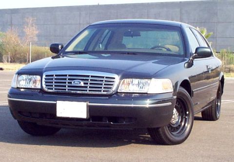
2001 Ford Crown Victoria/
Photo
supermotors.net/registry/media/539122
Ford Service Manual Illustration AN1751-A - Fastener Locations Diagram
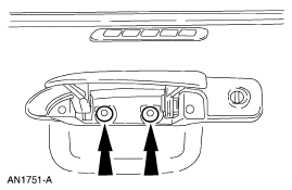
Service manual figure with arrows indicating two fastener locations (figure AN1751-A).
This document is a single service-manual illustration identified by the Ford figure number AN1751-A. It contains no descriptive text, tables, fuse data, or part numbers, only a black-and-white line drawing. The drawing depicts a component assembly (with what appears to be a slotted grille or vent above it and a small cylindrical element to the right, possibly a lock cylinder or fastener) viewed from below or in front. Two bold upward-pointing arrows call attention to two fasteners or attachment points on the underside of the assembly, indicating where a technician should remove or install screws/bolts during a removal-and-installation procedure. The image was uploaded to a 2001 Ford Crown Victoria gallery and is presumably one figure from a multi-page Ford workshop manual procedure (a companion figure, AN1726-A, is in the same album). Because the illustration carries no caption, year, model, or applicability statement, its exact subject and vehicle coverage cannot be confirmed from the image alone; readers can learn only the general fastener locations indicated by the arrows and the Ford illustration reference number for cross-referencing the full procedure in the factory service manual.
Is this accurate? Sign in to help verify it.
Frequently asked questions
- What is the figure number of this Ford service manual illustration?
- The illustration is identified as AN1751-A, shown in the lower-left corner of the image.
- What does the diagram indicate?
- Two large arrows point to two fastener locations on the underside of a component assembly, indicating attachment points relevant to a removal or installation step.
- Does this document list any part numbers, torque specs, or fuse information?
- No. The document contains only the line drawing and the figure identifier AN1751-A; no part numbers, torque values, or fuse data are shown.
- Does the illustration state which vehicle or model year it applies to?
- No. The image itself gives no year, model, or applicability information.
Comments
More from this build







No comments yet.