Home/
Registry/
Ford/
Crown Victoria/
1998-2011/
2001 Ford Crown Victoria/
Photo
supermotors.net/registry/media/528032
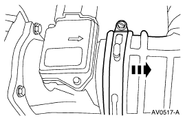
Ford Crown Victoria Air Intake / MAF Sensor Illustration - Manual Figure AV0517-A
Reference · 1998-2011 Crown VictoriaAll 18 manual pages
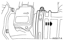


Service manual figure showing a component with directional install/remove arrows (figure AV0517-A).
Part of 1998-2011 Ford Crown Victoria Manual Pages
This document is a single black-and-white line illustration, typical of a Ford factory service manual or owner's guide figure, identified by the illustration code AV0517-A. The drawing depicts an under-hood component assembly: a rectangular housing (consistent with a mass air flow sensor or air cleaner assembly) connected to a large corrugated/ribbed air intake tube secured by a worm-gear hose clamp. Directional arrows are printed on both the housing and the tube, likely indicating airflow direction or alignment marks for proper installation. Two hex fasteners are shown attaching the housing to the vehicle structure. No captions, callout numbers, part numbers (other than the figure code), torque specifications, or descriptive text appear in the image, so the exact procedure it accompanies cannot be determined from the illustration alone. A reader can learn the general location and orientation of this intake-related component and see how the tube clamps to the sensor/housing, but any step-by-step instructions would be on an accompanying manual page not included in this scan.
Is this accurate? Sign in to help verify it.
Frequently asked questions
- What does this manual illustration show?
- It shows an under-hood component assembly, a rectangular housing (consistent with a mass air flow sensor or air cleaner assembly) connected to a ribbed air intake tube secured with a hose clamp, with arrows indicating airflow or alignment direction.
- What is the figure or illustration number on this page?
- The illustration code shown is AV0517-A.
- Are there any part numbers or torque specs in this document?
- No. The only text visible is the illustration code AV0517-A; there are no part numbers, torque values, or written instructions.
- What do the arrows in the drawing mean?
- Arrows appear on both the housing and the intake tube; they most likely indicate airflow direction or alignment orientation, but the drawing itself contains no explanatory caption.



No comments yet.