V-Engine Dual Plenum Induction System Patent Article - SH & Tell Summer 2001
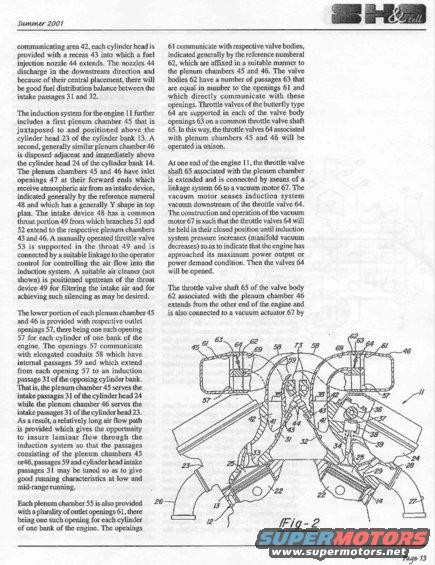
Magazine reproduction of an intake-system patent describing dual plenum chambers, fuel injection nozzles, and a manually operated throttle valve, with a labeled cross-section blueprint figure.
This document is page 13 of the Summer 2001 issue of a newsletter titled "SH & tell." It contains patent-style descriptive text (with an accompanying cross-sectional drawing labeled "Fig-2") explaining the design of a dual-plenum induction system for a V-type engine. The text describes how fuel injection nozzles (44) are centrally placed to balance fuel distribution between intake passages 31 and 32, and how two plenum chambers (45 and 46) sit above each cylinder head (23 and 24) of the two cylinder banks (13 and 14). A Y-shaped intake device (48) with a common throat (49) containing a manually operated throttle valve (53) feeds both plenums. Crossover conduits (58) route air from each plenum to the intake passages of the opposite cylinder bank, creating long air flow paths for laminar flow and good low- and mid-range tuning. Each plenum also has secondary outlets (61) feeding valve bodies (62) with butterfly throttle valves (64) on a common shaft (65), operated by vacuum motors (67) via linkage (66) that hold the valves closed until manifold vacuum drops at high power demand, then open them. Fig-2 shows the engine cross-section with all reference numerals. The document reads like an excerpt from a patent describing a variable/dual-stage intake manifold design.
Is this accurate? Sign in to help verify it.
Frequently asked questions
- What does this document describe?
- It describes a V-engine induction system with two plenum chambers (45 and 46) positioned above each cylinder head, a Y-shaped intake device (48) with a manually operated throttle valve (53), crossover conduits (58) feeding the opposite cylinder bank, and secondary butterfly throttle valves (64) operated by vacuum motors (67).
- Why do the plenum chambers feed the opposite cylinder bank?
- The crossover conduits (58) create a relatively long air flow path, which helps insure laminar flow through the induction system so the passages can be tuned to give good running characteristics at low and mid-range running.
- When do the secondary butterfly throttle valves 64 open?
- The vacuum motor 67 holds the throttle valves 64 closed until induction system pressure increases (manifold vacuum decreases), indicating the engine has approached its maximum power output or power demand condition; then the valves 64 are opened.
- Where are the fuel injection nozzles located?
- Each cylinder head has a recess 43 into which a fuel injection nozzle 44 extends. The nozzles discharge in the downstream direction, and their central placement provides good fuel distribution balance between intake passages 31 and 32.
- What issue and page is this from?
- It is from the Summer 2001 issue of a publication titled "SH & tell," page 13, and shows Fig-2, a cross-sectional drawing of the engine and induction system.
Comments
More from this build






No comments yet.