1993 Ford Taurus Fuse Box Diagram - Panel Layout, Flasher & Color Codes
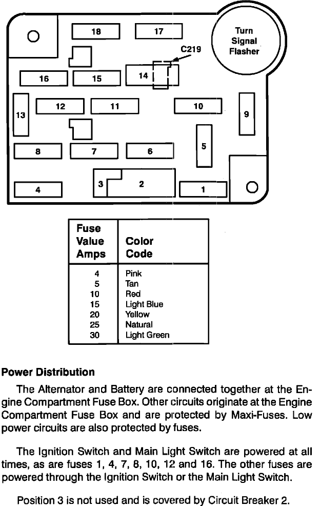
Interior fuse panel layout (positions 1-18) plus turn-signal flasher and connector C219, with a fuse amperage-to-color code chart and power-distribution notes.
This document is a fuse and relay panel layout diagram, uploaded to the gallery of a 1993 Ford Taurus. The diagram shows the physical arrangement of the interior fuse panel with 18 numbered fuse positions, a round Turn Signal Flasher mounted at the upper right corner, and a connector labeled C219 adjacent to fuse position 14. Below the diagram, a legend table translates fuse amperage values to their standard color codes: 4 amps = Pink, 5 amps = Tan, 10 amps = Red, 15 amps = Light Blue, 20 amps = Yellow, 25 amps = Natural, and 30 amps = Light Green. A 'Power Distribution' text section explains that the Alternator and Battery connect together at the Engine Compartment Fuse Box, where other circuits originate protected by Maxi-Fuses, with low-power circuits protected by regular fuses. It further notes that the Ignition Switch and Main Light Switch are powered at all times, as are fuses 1, 4, 7, 8, 10, 12 and 16, while the remaining fuses receive power through the Ignition Switch or Main Light Switch. Position 3 is not used and is covered by Circuit Breaker 2. Note the document itself does not assign circuit names or amp ratings to individual fuse positions and carries no explicit year/model identification.
Is this accurate? Sign in to help verify it.
Frequently asked questions
- Where is the turn signal flasher located on this fuse panel?
- The Turn Signal Flasher is the round component mounted at the upper right corner of the fuse panel, above fuse positions 9 and 10.
- What do the fuse colors mean on this panel?
- The legend lists: 4A = Pink, 5A = Tan, 10A = Red, 15A = Light Blue, 20A = Yellow, 25A = Natural, and 30A = Light Green.
- Which fuses are powered at all times?
- The document states that the Ignition Switch and Main Light Switch are powered at all times, as are fuses 1, 4, 7, 8, 10, 12 and 16. The other fuses are powered through the Ignition Switch or the Main Light Switch.
- What is fuse position 3 used for?
- Position 3 is not used and is covered by Circuit Breaker 2.
- What is C219 on the diagram?
- C219 is a connector callout on the diagram, indicated by an arrow pointing to the area at fuse position 14.
Comments
More from this build










No comments yet.