Home/
Registry/
Ford/
C-350 (Centurion Conversions)/
“white”/
Photo
supermotors.net/registry/media/606203
1995 Ford Diesel High Idle Switch Wiring Diagram - DPDT Relay & TPS/IVS Mod
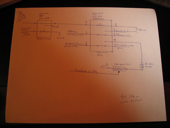
Hand-drawn wiring diagram showing a DPDT relay, brake interlock, TPS feed and 1k-ohm resistor for a diesel high-idle control.
This is a hand-drawn wiring diagram documenting a homemade high-idle control modification for a 1995 Ford diesel (captioned "High Idle on White '95 Diesel"). The circuit uses two Radio Shack components: an SPDT switch (part 275-248) serving as the high-idle on/off switch with a brake interlock (fed by switched +12V and by the brake light switch's +12V-when-pedal-pressed signal), and a DPDT relay (part 275-218) labeled "Idle control Relay." The relay's numbered pins (1-8) are shown: pin 7 receives the switched feed, pin 8 goes to ground, pin 5 receives the red/orange wire from the harness to the IVS, pin 1 connects to red/orange on the IVS, pin 3 is spliced into brown on the IVS, pin 6 receives brown/white from the harness to the TPS, and pin 2 splices to brown/white on the TPS. Pin 4 feeds through a 1k-ohm resistor into an "Idle speed control" potentiometer whose wiper connects to grey/white on the TPS. A reader can learn the exact wire colors (red/orange, brown, brown/white, grey/white), the relay pinout, part numbers, and the resistor value needed to replicate this high-idle setup with brake-pedal cutout.
Is this accurate? Sign in to help verify it.
Frequently asked questions
- What Radio Shack parts are used in this high idle circuit?
- A Radio Shack SPDT switch, part 275-248 (used as the high idle on/off switch with brake interlock), and a Radio Shack DPDT relay, part 275-218 (used as the idle control relay).
- Which TPS wires are tapped for the high idle modification?
- The brown/white wire from the harness to the TPS is run through relay pins 6 and 2 (spliced at the TPS), and the grey/white wire on the TPS connects to the wiper of the idle speed control potentiometer.
- How is the brake interlock wired?
- The brake light switch signal (+12V when the pedal is pressed) feeds the SPDT switch/brake interlock section, which controls the +12V feed to relay pin 7; relay pin 8 goes to ground.
- What resistor value is used with the idle speed control?
- A 1k ohm resistor is wired in series between relay pin 4 and the idle speed control potentiometer.
- Which IVS wires are involved?
- The red/orange wire from the harness to the IVS goes to relay pin 5, pin 1 connects to red/orange on the IVS, and pin 3 is spliced into the brown wire on the IVS.
Comments
More from this build
No comments yet.