Home/
Registry/
Ford/
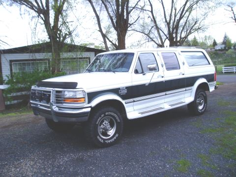
C-350 (Centurion Conversions)/
“white”/
Photo
supermotors.net/registry/media/606236
1995 Ford Diesel High Idle Wiring Diagram - DPDT Relay & TPS/IVS Mod Schematic
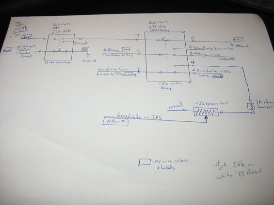
Hand-drawn wiring diagram of a diesel high-idle relay circuit annotated with wire colors and harness labels.
This is a hand-drawn wiring diagram documenting a DIY high-idle circuit installed on a white 1995 diesel truck. The circuit uses two RadioShack components: a 275-248 SPDT switch/relay used as a brake interlock and a 275-218 DPDT relay used as the idle control relay. Switched +12V (labeled Red, 'High Idle on/off') feeds through the brake interlock, which is controlled by the brake light switch (+12V when the pedal is pressed, purple wire), so the high idle disengages when braking. The DPDT relay pins are numbered 1-8: pin 7 receives the switched power, pin 8 goes to ground (black), pin 3 splices into the brown wire on the IVS (idle validation switch), pin 5 connects to red/orange from the harness to the IVS, pin 1 to red/orange on the IVS, pin 6 to brown/white from the harness to the TPS, pin 2 to brown/white on the TPS splice, and pin 4 routes through a 1k ohm resistor to an idle speed control potentiometer whose wiper ties to grey/white on the TPS. Boxed labels indicate the builder's own wire colors (Red, Purple, Blk, Blue, Green #1, Green #2, BRN/WHT, Yellow #1). Useful for anyone replicating a manual high-idle mod on a mid-90s Ford diesel.
Is this accurate? Sign in to help verify it.
Frequently asked questions
- What relays are used in this high idle circuit?
- Two RadioShack parts: a 275-248 SPDT used as the brake interlock and a 275-218 DPDT relay used as the idle control relay.
- How does the brake interlock work in this diagram?
- The brake light switch supplies +12V when the pedal is pressed, controlling the SPDT brake interlock so the switched +12V high-idle feed is interrupted; the other side of the interlock coil goes to ground (black wire).
- Which TPS and IVS wires are tapped for the high idle mod?
- Red/orange from the harness to the IVS (relay pins 5 and 1), brown wire on the IVS (spliced at pin 3), brown/white from the harness to the TPS (pin 6) and brown/white on the TPS splice (pin 2), plus grey/white on the TPS to the idle speed control potentiometer wiper.
- What resistor value is used with the idle speed control?
- A 1k ohm resistor is wired between DPDT relay pin 4 and the idle speed control potentiometer.
- What vehicle is this diagram for?
- The diagram is labeled 'High Idle on White '95 Diesel'.
Comments
More from this build
No comments yet.