Home/
Registry/
Ford/
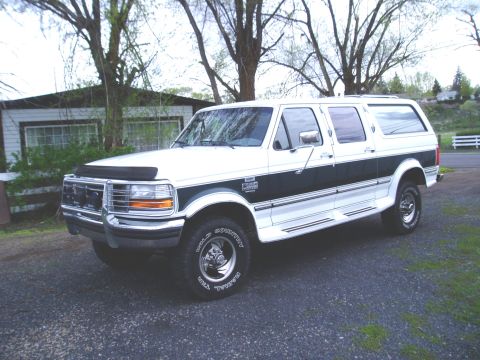
C-350 (Centurion Conversions)/
“white”/
Photo
supermotors.net/registry/media/606204
1995 Ford Diesel High Idle Wiring Diagram - DPDT Relay, TPS & IVS Mod
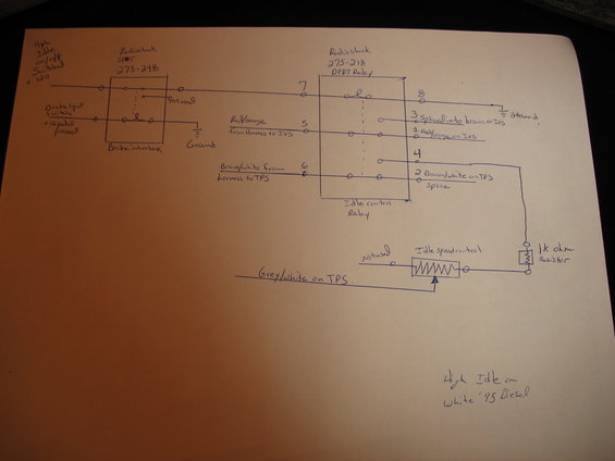
Hand-drawn wiring diagram showing a DPDT relay, brake interlock, idle-control and 1k-ohm resistor for a diesel high-idle setup.
This is a hand-drawn wiring diagram titled "High Idle on White '95 Diesel," showing how to add a switchable high-idle circuit to a 1995 Ford diesel. A switched +12V "High Idle on/off" feed passes through a Radio Shack SPDT switch (part 275-248), which is wired as a brake interlock using the brake light switch (+12V when pedal pressed) so the high idle disengages when braking. That circuit energizes a Radio Shack 275-218 DPDT relay (labeled "Idle control Relay") via terminal 7, with terminal 8 grounded. The relay's switched contacts intercept two signal wires: the red/orange wire from the harness to the IVS (terminal 5, normally passed to terminal 1 "Red/orange on IVS," with terminal 3 spliced into brown on IVS) and the brown/white wire from the harness to the TPS (terminal 6 to terminal 2 "Brown/white on TPS splice"). When the relay activates, terminal 4 routes through a 1k ohm resistor to an "Idle speed control" potentiometer, whose wiper connects to the grey/white wire on the TPS, allowing adjustable high idle speed. One switch and one pot terminal are marked "Not used."
Is this accurate? Sign in to help verify it.
Frequently asked questions
- What relay is used for this high idle circuit?
- A Radio Shack 275-218 DPDT relay, labeled in the diagram as the Idle control Relay.
- How is the brake interlock wired?
- A Radio Shack SPDT switch (275-248) is wired between the high idle on/off switched +12V feed and the brake light switch (+12V when pedal pressed), so the relay coil circuit acts as a brake interlock; one switch terminal is not used and the other side goes to ground.
- Which TPS and IVS wires are tapped for the high idle mod?
- The red/orange wire from the harness to the IVS (relay terminals 5 to 1, with terminal 3 spliced into brown on the IVS), the brown/white wire from the harness to the TPS (terminals 6 to 2), and the grey/white wire on the TPS which connects to the idle speed control potentiometer wiper.
- What resistor value is used in the idle speed control circuit?
- A 1k ohm resistor is placed between relay terminal 4 and the idle speed control potentiometer.
- What vehicle does this diagram apply to?
- The diagram is labeled "High Idle on White '95 Diesel."
Comments
More from this build

No comments yet.