Ford TSB 96-13-07 A/C cable diagram with control head and author…
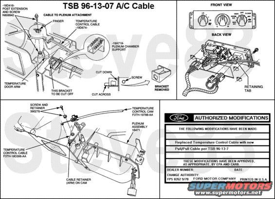
TSB 96-13-7 AIR CONDITIONING/HEATER - LOW OR NO HEAT/AIR CONDITIONING - HIGH EFFORT TO TURN TEMPERATURE CONTROL KNOB - POOR TEMPERATURE MODULATION - LOW OR NO HEAT/COOLING - VEHICLES BUILT THROUGH 2/27/95
Publication Date: JUNE 17, 1996
LIGHT TRUCK: 1992-1995 BRONCO, F-150-350 SERIES, F-47
ISSUE: The temperature control knob may be difficult to turn on some vehicles. There may also be a low or no heat/cooling condition accompanied by poor temperature modulation. This may be caused by the single cable temperature door operating system being used.
ACTION: Replace the A/C Temperature Control Cable Assembly with a new pull/pull cable design. The new design cable will provide improved control of the temperature door. Refer to the following Diagnostic and Replacement Procedures for details.
DIAGNOSTIC PROCEDURE
1. If the vehicle exhibits high effort turning the temperature control knob or poor temperature modulation, a new cable must be installed. Refer to the Replacement Procedure listed in this article. For a low or no heat/cooling concern, continue on with the Diagnostic Procedure.
2. Check vehicle's coolant for the correct level, concentration and operating temperature with the thermostat open. If a concern is found in one (1) of these areas, refer to the appropriate Service Manual for repair procedures. The repairs must be done before proceeding.
3. Verify proper A/C system charge and operation. Repair as necessary.
4. If the concern still exists, perform the Cable Adjustment procedure listed in the appropriate F-Series/Bronco Service Manual, Section 12.
5. If the concern still exists, replace the temperature door cable. Refer to the following Replacement Procedure for details.
REPLACEMENT PROCEDURE
REMOVAL
1. Remove glove compartment and module assembly, if present.
2. Detach cable from plenum using Tool D91T-18532-A. Remove and discard cable.
3. At the cable bracket on the plenum heater core cover, cut away the bracket using a hacksaw blade or similar tool.
4. Remove the 5/16" headed screw from the top of the cam. Discard the cam and screw with spring clip.
5. At cam post, add post extension and secure with the new screw, torquing the screw to 1.7 N-m (15 lb-in).
6. Remove the upper left screw securing the plenum heater core cover and install the A/C plenum chamber support bracket between the ribs to the right side of the bracket which was cut off. Make sure the hole from the previously removed screw is lined up with the hole in the plenum chamber support bracket.
INSTALLATION
1. At the plenum chamber, move the temperature door arm to the "full warm" position (counterclockwise) and be sure it remains there throughout the installation procedure.
2. At the small end of the cable (control head), remove the temperature control bracket from the cable by releasing the three (3) snaps using Tool T94P-18532-A or a thin blade screwdriver to allow the cable to be pushed back through the instrument panel toward the control head.
3. Be sure the new pull/pull cable is in the "full warm" position. Check the molded-in arrow at the control head portion of the cable. Normally the cable is shipped in the "full warm" position.
4. At the plenum, position the cam end of the cable over the post. Make sure the temperature door arm can move into the slot of the cam and push down until the cam is engaged on the post. An audible click can be heard. If it is necessary to remove the cam cable head, use moderate finger pressure on the plastic tab at the top of the cam cable head, moving it back so the cam may be pulled out off the post.
5. Place the twin cables in the center slots of the A/C plenum chamber support bracket. If adjustment is needed later, the cables can be moved to the other adjacent slots.
6. Route new cable through the instrument panel following the same path as the old cable.
7. Check the new temperature control bracket to be sure it is in the "full warm" position. The tab should be in the slot in the bracket.
8. Push the temperature control bracket onto the control assembly and turn it to catch under the retaining tab. Secure with the new screw previously saved.
9. Place the knob on the temperature control.
10. Push the cable head onto the temperature control bracket (make sure gear pilot centering hole is lined up correctly) until the three (3) lock into position (you should hear a click of three (3) tabs).
11. Install temperature control assembly in instrument panel.
12. Swiftly rotate temperature control knob to each extreme (cool-warm) and listen for the sound of the temperature door closing in both directions. If no audible close is heard, move the cable into different slots at the A/C plenum chamber support bracket covered in Step 4 of the Installation Procedure until there is an audible close in each direction.
13. Bring vehicle to operating temperature and verify proper heating and cooling by measuring the temperature of the discharge air at the outlets.
14. At A/C plenum chamber support bracket, secure cable to bracket with a tie strap to keep cable in place.
Obtain an Authorized Modifications Decal and list the date, dealer number, and summary of alterations performed. Select a prominent place adjacent to the Vehicle Emission Control Information Decal suitable for installing the Authorized Modifications Decal. Clean the area, install the decal, and cover it with a clear plastic decal shield.
The Temperature Control Cable Kit (F5TZ-19988-CA) consists of:
One (1) Temperature Control Cable
One (1) Temperature Control Bracket
One (1) Plenum Support Bracket
One (1) Post Extension
One (1) Screw
One (1) Tie Strap
One (1) Instruction Sheet (I.S. #6630A)
PART NUMBER: Temperature Control Cable Kit
PART NAME: F5TZ-19988-CA
OTHER APPLICABLE ARTICLES: NONE
WARRANTY STATUS: Eligible Under The Provisions Of Bumper To Bumper Warranty Coverage
OPERATION: 961307A
DESCRIPTION: Install Pull/Pull Cable Retrofit Kit
TIME: 0.8 Hr.
For other TSBs, check here.
See also: .
.  .
.  .
.  .
.  .
.  .
.  .
. 
Is this accurate? Sign in to help verify it.
Comments
More from this build


No comments yet.