Home/
Registry/
Mercury/
Cougar/
1989-1997/
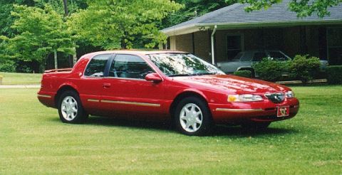
1997 Mercury Cougar/
Photo
supermotors.net/registry/media/713107
Ford/Mercury Instrument Cluster Wiring Diagram 63-3: SCP, PATS, Brake Warning
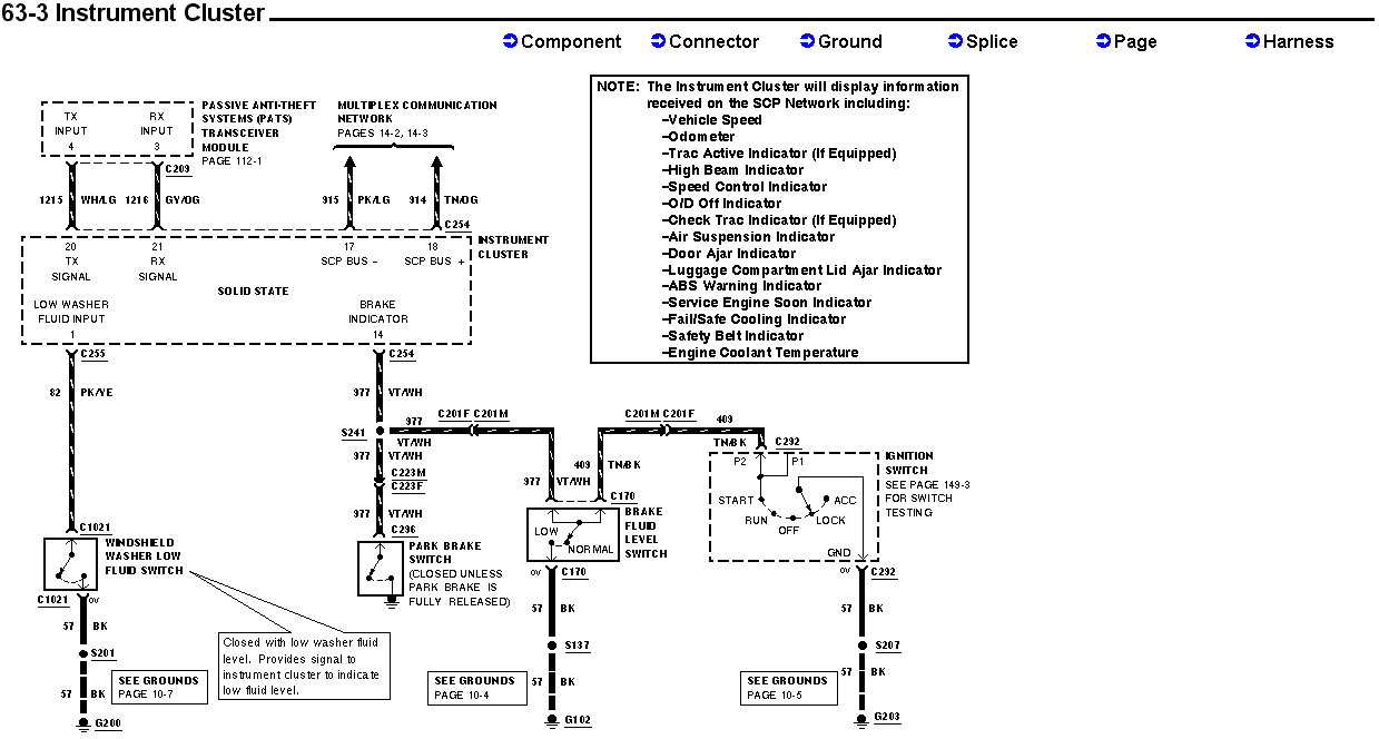
Ford instrument cluster wiring (page 63-3): SCP network 315 PK/LG and 314 TN/OG, PATS TX/RX, low washer-fluid and brake-fluid switch circuits to grounds G200/G102/G203.
Part of 1989-1997 Mercury Cougar Wiring Diagrams
This is page 63-3 of a Ford factory-style wiring diagram covering the Instrument Cluster circuit. It shows the solid-state instrument cluster and its connections: PATS transceiver module TX/RX signals (circuits 1215 WH/LG and 1216 GY/OG through connector C209 to cluster pins 20 and 21), the multiplex communication (SCP) network bus lines (915 PK/LG and 914 TN/OG to pins 17 and 18 via C254), the low washer fluid input (circuit 82 PK/YE via C255 and C1021 to the windshield washer low fluid switch, grounded through 57 BK at S201/G200), and the brake indicator circuit (pin 14, circuit 977 VT/WH) feeding both the park brake switch (via C223M/C223F and C236) and the brake fluid level switch (via C201F/C201M and C170, grounded at S137/G102). A branch on circuit 409 TN/BK runs through C292 to the ignition switch (START/RUN/OFF/ACC/LOCK), grounded through 57 BK at S207/G203. A note lists all information the cluster displays over the SCP network, including vehicle speed, odometer, various warning indicators, and engine coolant temperature. Cross-references point to pages 112-1 (PATS), 14-2/14-3 (multiplex network), 149-3 (ignition switch testing), and grounds pages 10-4, 10-5, and 10-7.
Is this accurate? Sign in to help verify it.
Frequently asked questions
- What wire colors connect the PATS transceiver to the instrument cluster?
- Circuit 1215 WH/LG (white/light green) carries the TX input to cluster pin 20, and circuit 1216 GY/OG (gray/orange) carries the RX input through connector C209 to cluster pin 21.
- Which cluster pins are the SCP data bus wires?
- SCP BUS: is pin 17 (circuit 915 PK/LG) and SCP BUS + is pin 18 (circuit 914 TN/OG), connecting through C254 to the multiplex communication network.
- What wire triggers the brake warning indicator in the cluster?
- Circuit 977 VT/WH (violet/white) from cluster pin 14 through C254; it splices at S241 and runs to both the park brake switch (via C223M/C223F and C236) and the brake fluid level switch (via C201F/C201M and C170).
- How does the low washer fluid warning work?
- The windshield washer low fluid switch closes with low washer fluid level, providing a signal on circuit 82 PK/YE to cluster pin 1 (LOW WASHER FLUID INPUT); the switch grounds through circuit 57 BK at S201 to G200.
- What information does the instrument cluster receive over the SCP network?
- Vehicle speed, odometer, Trac Active indicator (if equipped), high beam indicator, speed control indicator, O/D Off indicator, Check Trac indicator (if equipped), air suspension indicator, door ajar indicator, luggage compartment lid ajar indicator, ABS warning indicator, Service Engine Soon indicator, fail/safe cooling indicator, safety belt indicator, and engine coolant temperature.
Comments
More from this build

No comments yet.