Range Rover Classic EAS electronic air suspension wiring diagram…
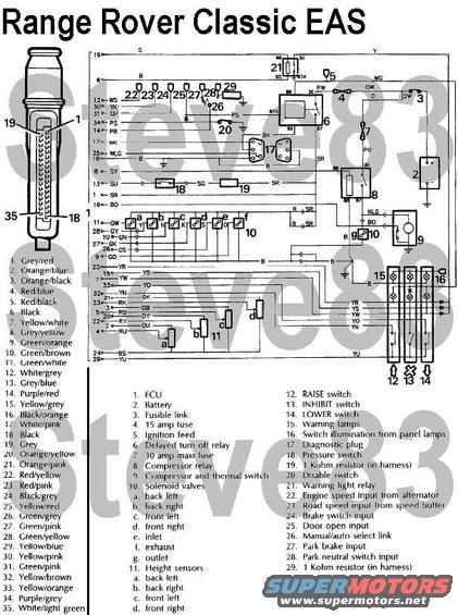
Electronic Air Suspension for Range Rover Classic
For plumbing, see:

RANGE ROVER ELECTRONIC AIR SUSPENSION (EAS)
Description
The electronic air suspension is a versatile microprocessor controlled system that exploits the advantages of air suspension. It provides a variable spring rate, which achieves near constant ride frequency for all load conditions, giving:
> Improved ride quality.
> Continuity of ride quality, laden or unladen.
> Constant ride height.
> Improved headlamp leveling.
The function of the system is to provide five height modes, each of which is automatically maintained at the given height by the system logic with the minimum of driver involvement. Vehicle height is sensed by four rotary potentiometer type height sensors. Vehicle height information from each potentiometer signals the ECU to adjust each air spring by switching the solenoid valves to hold, add or release air. The system provides five height settings and automatic self-leveling as follows:
> Standard - standard ride height i.e. 790 mm /-7 mm, measured from centre of wheel arch eyebrow to floor.
> Low profile: 20 mm below standard.
> Access: 60 mm below standard.
> High profile: 40 mm above standard.
> Extended profile: 10 to 30 mm above high profile.
Self-Leveling
The system provides self-leveling under varying vehicle loads. The vehicle will self level to the lowest corner height level for 10 seconds after switching off engine, exiting vehicle and closing doors.
Standard
Vehicle ride height is tile same as with conventional suspension, but is maintained under all load conditions. This also provides improved headlamp leveling.
Low profile
This position gives improved handling and fuel consumption at high speed. When the vehicle speed exceeds 80 kph (50 mph) for more than 30 seconds, with INHIBIT switch off, the vehicle will enter the low profile position. The vehicle will return to standard height when vehicle speed drops below 56 kph (35 mph) for more than 30 seconds, unless vehicle stops, in which case it returns to standard when driven away. The LOWER lamp is illuminated in this condition.
Access
This position makes passenger boarding and luggage loading easier. With the vehicle stationary, park brake on (manual) or P selected (automatic), footbrake off, doors closed, and INHIBIT switch off, pressing the LOWER switch will select the ACCESS position. It is possible to select access for 15 seconds after switching engine off. The LOWER lamp flashes until access position is reached, when it remain constantly illuminated.
NOTE: Opening a door will freeze vehicle position.
From access, the vehicle will return to standard ride height if the RAISE switch is pressed, OR inhibit switched on, OR park brake released, OR the vehicle driven off.
High profile
This position is used to improve approach and departure angles and when wading. Pressing the RAISE switch will select this position provided the road speed is below 56 kph (35 mph) with INHIBIT off. The vehicle will return to standard position when road speed exceeds 56 kph (35 mph) or LOWER switch is pressed. The RAISE lamp is illuminated in this condition.
NOTE: When raising ride height, rear of vehicle will raise by 70% of movement first followed by 70% of front. Rear will raise remaining 30% before front. Lowering will be achieved by lowering front of vehicle first. This will ensure that, with headlamps illuminated, there is no inconvenience from headlamp dazzle to other road users. BUT, lowering to access position will be achieved by the fastest possible means, by opening all air valves at the same time.
Extended profile
This position is achieved when vehicle is off road in standard or high profile and the chassis is grounded leaving wheels unsupported. Initial ECU reaction is to deflate (lower) affected springs. After a timed period ECU detects no height change, therefore it reinflates springs in an attempt to regain traction. The RAISE lamp will flash in this mode. After ten minutes system will return to high profile, unless LOWER switch is pressed.
Component Description
Electrical control unit - ECU
The ECU is located underneath the right hand front seat, on top of the fuel ECU. It maintains the requested vehicle ride height by adjusting the volume of air in each air spring. It is connected to the cable assembly by a 35-way connector. To ensure safe operation the ECU has extensive on board diagnostic and safety features. The ECU is non-serviceable. In case of failure it must be replaced.
Power supply for the system consists of the following components:
1. Delayed power turn off relay. This remains powered up for 10 seconds after exiting vehicle to allow self-leveling.
2. Compressor relay, 4 pins.
3. Warning light relay, 5 pins.
4. 30 amp 'maxi fuse' for compressor power.
5. 15 amp fuse for ECU pin 1.
The disable switch is mounted under the right hand front seat. The switch has no markings; in the DISABLE position the bottom of the switch is pushed in. It is used to disable system when vehicle is being delivered, or when working on the system after depressurizing. The switch disables the system at speeds below 56 kph (35 mph).
Height sensors
Four potentiometer type height sensors signal vehicle height information to the ECU. The potentiometers are mounted on the chassis and activated by links to the front radius arms and rear trailing links. In case of height sensor failure, the assembly must be replaced.
Control Switches
Mounted on the lower fascia, three control switches are arranged thus:
1 - Raise - momentary touch switch
2 - Inhibit - self-latching switch, when switched on the vehicle will remain at standard ride height. This position is used when the automatic height adjustment is not required, i.e. when towing. Self leveling will continue to function.
3 - Lower - momentary touch switch
The switches incorporate a warning lamp. When engine is started all three warning lamps will illuminate for three seconds as part of bulb check. The switches are illuminated when the vehicle lights are on, controlled by the dimmer switch. The following components are contained in the AIR SUPPLY UNIT mounted on the right hand chassis side: AIR COMPRESSOR, AIR DRYER, and VALVE BLOCK.
Air compressor
The air compressor provides system pressure. A thermal switch is incorporated which switches off the compressor relay earth at 130°C. The compressor has an air intake silencer mounted behind rear mud flap. The air intake filter is located adjacent to the fuel filler flap. The filter is renewed every 40,000 km/24,000 miles/24 months (30,000 miles USA).
Air dryer
The air dryer is connected into the air line between compressor and reservoir. It removes moisture from pressurized air entering the system. When air is exhausted from the system, it passes through the dryer in the opposite direction. The air dryer is regenerative in that air absorbs moisture in the dryer and expels it to atmosphere.
The air dryer unit is non-serviceable, designed to last the life of the vehicle. However if water is found in the system when reservoir drain plug is removed, the air dryer must be changed.
CAUTION: If the air dryer is removed from the vehicle, the ports must be plugged to prevent moisture ingress.
Valve block
The valve block controls the direction of air flow. Air flow to and from the air springs is controlled by six solenoid operated valves, one for each air spring, one inlet and one exhaust. A diaphragm valve operated by the solenoid outlet valve ensures that all exhausted air passes through the air dryer. In response to signals by the ECU, the valves allow high-pressure air to flow in or out of the air springs according to the need to increase or decrease pressure. The valve block is non-serviceable; in case of failure, it must be replaced.
Non-return valves
The valve block contains three non-return valves. NRVl retains compressor air pressure by preventing flow back to the compressor.
NRV2 prevents loss of pressure in the system if reservoir pressure drops. It also ensures correct - flow through the inlet valve.
NRV3 ensures correct flow through the exhaust valve.
Reservoir
The 10-liter reservoir is mounted on the left hand side of the chassis. One connection acts as inlet and outlet to the rest of the system. It stores compressed air between set pressure levels. The reservoir drain plug requires removing every 40,000 km/24,000 miles/24 months (30,000 miles USA) to check for moisture in the system. See: Repair, air
reservoir - drain.
Pressure switch
Mounted on the reservoir is a pressure switch which senses air pressure and signals the ECU to operate the compressor when required. The compressor will operate when pressure falls to between 7.2 and 8.0 bar. It will cut out at a rising pressure of between 9.5 and 10.5 bar.
Air springs components
I. Top plate
2. Rolling rubber diaphragm
3. Piston
The air springs are mounted in the same position as conventional coil springs. Front and back air springs are of similar construction, but are not interchangeable. The diaphragm is NOT repairable; if failure occurs, the complete unit must be replaced.
AIR PIPE COLOR CODES
The following pipes have a colored band to aid assembly:
Component - Color
Back left spring - Red
Back right spring - Blue
Front left spring - Yellow
Front right spring - Green
Reservoir - Brown
Exhaust - Violet
SYSTEM OPERATION
Air is drawn through the inlet filter (1) to the compressor (2), where it is compressed to 10.0 f 0.5 bar.
Compressor operation activates the diaphragm solenoid valve (12) to prevent air going straight to atmosphere.
Compressed air passes to the air dryer (3). Moisture is removed as air flows through the dryer desiccant. The desiccant in the dryer becomes wet.
Dried air passes to the valve block, through NRVI to the reservoir (4).
The three non-return valves (6) ensure correct air flow. They also prevent loss of spring pressure if total loss of reservoir pressure occurs.
A pressure switch (5) maintains system pressure between set limits by switching the compressor on and off via an ECU-controlled relay.
For air to be admitted to any spring or springs, inlet valve (7) and the relevant air spring solenoid valve or valves (9) must be energized.
For air to be exhausted from any spring, the exhaust valve ( 8 ) and the relevant air spring solenoid valve or valves must be energized.
The diaphragm solenoid valve ensures that air exhausted to atmosphere passes through the dryer. This action purges moisture from the desiccant and regenerates the air dryer.
Air is finally exhausted through the system-air-operated diaphragm valve (13) and to atmosphere through a silencer (14) at the chassis rear crossmember.
ECU INPUTS
The air suspension system is controlled by the ECU, which operates dependant on driver-selected inputs plus those listed below. In each mode the ECU maintains the requested ride height by adjusting the volume of air in one or more of the air springs.
Battery - 12 volt supply from ignition load relay.
Engine - from alternator phase tap, signals engine speed to ECU. Note that engine must be running for all height changes, except access and self-leveling when parked The compressor will be disabled if engine speed falls below 500 rev/min. This is to prevent the compressor drawing current from the battery when the alternator is not charging.
Height sensors four potentiometer height sensors provide suspension height signals to the ECU.
Road speed - the road speed transducer provides information enabling height changes to occur at correct road speed. Input speed signal to ECU is from a buffer unit located in the driver's side foot well.
Interior light delay unit - signals ECU if any door (not tailgate) is opened, which immediately suspends all height changes.
Park brake switch, manual vehicles the park brake must be ON to enter ACCESS
Gearbox inhibit switch, automatic vehicles - the transmission must be in park to enter access, park brake on or off.
Footbrake switch (brake light) - when footbrake is applied, and for one second after release, all height leveling is suspended below 1.6 kph (1 mph) and above 11 kph (5 mph). The purpose of this is to prevent the system reacting to suspension movement caused by weight transfer during braking and to prevent suspension windup during height change. Note that this inhibit function is removed after sixty seconds; e.g. if footbrake is held on for this time.
Delayed turn off relay remains energized after switching engine off and exiting vehicle, enables self-leveling to occur for 20 sec. If vehicle is stationary, the ECU will energize the relay every six hours to allow self-leveling to occur if necessary.
Reservoir pressure switch - when the ECU detects an output from the pressure switch indicating low pressure, the ECU will operate the compressor relay until the pressure switch indicates normal pressure.
Diagnostic plug ground - note that the two halves of the diagnostic plug are normally connected. When disconnected the system will not operate. It will remain frozen at its current height until reconnected.
Disable switch - In the disable position, the switch sends a door open signal to the ECU. This freezes the system in position at speeds below 56 kph (35 mph).
SYSTEM FUNCTION
The following table indicates conditions required for various air suspension modes.
NOTE: That the engine must be running unless indicated, and that ACCESS may be selected for 15 seconds after switching engine off.
Function - Condition - Warning lamp on
1. Automatic functions - Inhibit switch OFF.
High profile to standard - Over 56 kph (35 mph) - No
Standard to low profile - Over 80 kph (50 mph) for 30 sec - Lower
Low profile to Standard - Below 56 kph (35 mph) for 30 sec (but above 1.6 kph (1 mph)) - No
Access to standard - Park brake off or drive away - No
2. Driver select functions - Inhibit switch OFF.
Standard to high profile - Raise switch below 56 kph (35 mph) - Raise
High profile to standard - Lower switch below 56 kph (35 mph) - No
Standard to access - Lower switch )Stationary - Lower
)park brake on
Low profile to access - Lower switch )- manual/ - Lower
(where vehicle has not returned to standard )transmission P
)- automatic
High to Access - Press lower switch twice )doors shut - No
Access to standard - Raise switch - Lower
Access to high - Press raise switch twice - Raise
3. Inhibit switch ON
High profile to standard - Below 56 kph (35 mph) - Inhibit
Low profile to standard - - Inhibit
Access to standard - Stationary/park brake on - Inhibit
4. Self-leveling
Vehicle leveling for 20 sec, and every 6 hrs - Stationary/engine off/exit vehicle - No
DIAGNOSTICS AND FAULT RECOVERY
The ECU incorporates Fault Recovery Strategies to minimize the effect of a system failure. A serial data link is provided to allow diagnostic information to be retrieved using the Lucas hand held tester. This is also used to set height sensor datum when required.
Note that the serial link connector is colored black for identification purposes. Any faults stored in the ECU memory (from the previous or current running period) will cause the ECU to flash the RAISE and LOWER lamps for 30 sec. followed by continuous illumination.
If the ECU registers a system fault, it will store the fault in the memory. The fault recovery program will operate the system depending on the nature of the fault as follows:
Speed sensor fault - the ECU will place the system in standard height and activate inhibit.
Height sensor fault the ECU will place the system in standard height and activate inhibit. Note that if more than one height sensor fails, the ECU will deflate the air springs to the bump stops.
WARNING: If any two failures occur, the system deflates and lowers vehicle to its bump stops. It is possible to drive the vehicle provided that great caution is exercised. The vehicle ride will be extremely uncomfortable and only low speeds will be possible. It is essential that the vehicle fault be rectified as soon as possible.
Pressure switch fault - the ECU will register pressure switch failure if it detects that the compressor has worked for a programmed time with normal air spring operation possible. The ECU will periodically operate the compressor as air is required. The vehicle will be inhibited to standard.
Compressor fault - the ECU will register compressor failure if it detects that the compressor has worked for a programmed time with normal air spring operation not possible. The ECU will attempt to place the system in standard ride height, or a safe lowered position (which could be system deflated). The system will be inhibited from further ride height changes.
Air leaks - during normal operation, the ECU correlates the operating time of the compressor with air usage. If compressor use is greater than programmed, the ECU will register an air lank and attempt to place the system in standard ride height, or a safe lowered position (which could be system deflated). The system will be inhibited from further ride height changes.
Valve block fault - the control of each air spring is monitored to determine that every valve is working correctly.
1. If the ECU detects an air valve stuck open, it will attempt to adjust the vehicle to standard height or a safe lowered position (which could be system deflated). The system will be inhibited from further ride height changes.
2. If an air valve is stuck closed above standard height, the ECU will deflate the other three air springs.
3. If an air valve is stuck closed at or below standard height, the ECU will attempt to adjust the other springs to the same height and activate inhibit.
SUSPENSION COMPONENTS
This section gives repair procedures for air suspension components. It is essential to note that repairs to other suspension and transmission components are affected by air suspension. To remove the following components, depressurize the system: front axle, panhard rod, radius arms, rear top and bottom links, and rear axle.
WARNING: The air spring must be restricted by suspension loading, with shock absorbers fitted before inflation. Unrestricted movement of a pressurized air spring will result in failure of the assembly, causing component and possible personal injury.
DEPRESSURIZE SYSTEM
Service repair no - 60.5038
Service tool: RTC 6834 - Lucas hand held tester
WARNING: Air suspension is pressurized up to 10 bar. Dirt or grease must not enter the system. Wear hand, ear and eye safety standard protection when servicing system.
1. Depressurizing system will lower body on to bump stops.
2. Connect hand held tester and follow manufacturer's instructions to depressurize complete system.
3. Ensure system is completely depressurized. Check that all air springs are deflated and vehicle has dropped evenly to the bump stops. If a spring or springs remains inflated possibly due to a stuck solenoid valve, it will be necessary to disconnect the pressurized pipe at air spring.
WARNING: Wear hand, ear and eye safety standard protection. For extra protection wrap a clean cloth around pipe to be disconnected. Note that vehicle will lower to bump stops when pipe is disconnected.
4. Disconnect air pipe see disconnect/connect air pipe.
5. Disable system using switch under right hand front seat.
Repressurize
6. Switch disable switch OFF.
7. Run engine to repressurize system.
AIR RESERVOIR - DRAIN
Service repair no - 50.50.24
The reservoir is drained every 30,000 Km (24,000 miles) - USA 30,000 miles.
1. Depressurize system.
2. Clean area around reservoir drain plug.
3. Partially open drain plug, allow residual air to escape.
4. Remove drain plug, NO water should be present. If water is present, air dryer unit must be changed.
5. Fit drain plug, checking sealing washer. Tighten to 70 Nm.
6. Repressurize system.
LEAK TEST PROCEDURE
Service repair no - 60.50.35
If an air leak is suspected the USE of a proprietary leak detection spray is recommended. This procedure should also be used where pneumatic components have been disturbed. The spray used must have a corrosion inhibitor, and must not cause damage to paintwork, plastics, metals, and plastic pipes.
Recommended leak detector spray is GOTEC LDS. This is available under part number STC 1090.
1. Ensure system is fully pressurized.
2. Clean around area of suspected leak.
3. Using manufacturer's instructions, spray around all component joints and air springs, working systematically until source of leak is found.
4. If a component e.g.: air spring, air dryer is leaking, rectify by fitting a new component.
5. If an air pipe connection is leaking cut 5 mm off end of pipe. Fit new collet.
6. Reinflate system; carry out leak test.
Is this accurate? Sign in to help verify it.
Comments
More from this build


No comments yet.