Home/
Registry/
Ford/
Ranger/
1983-1992/
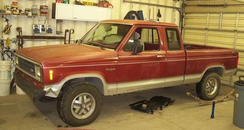
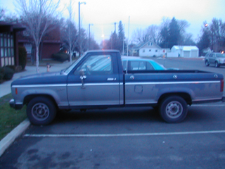
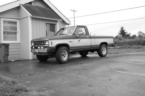
1990 Ford Ranger/
Photo
supermotors.net/registry/media/799642
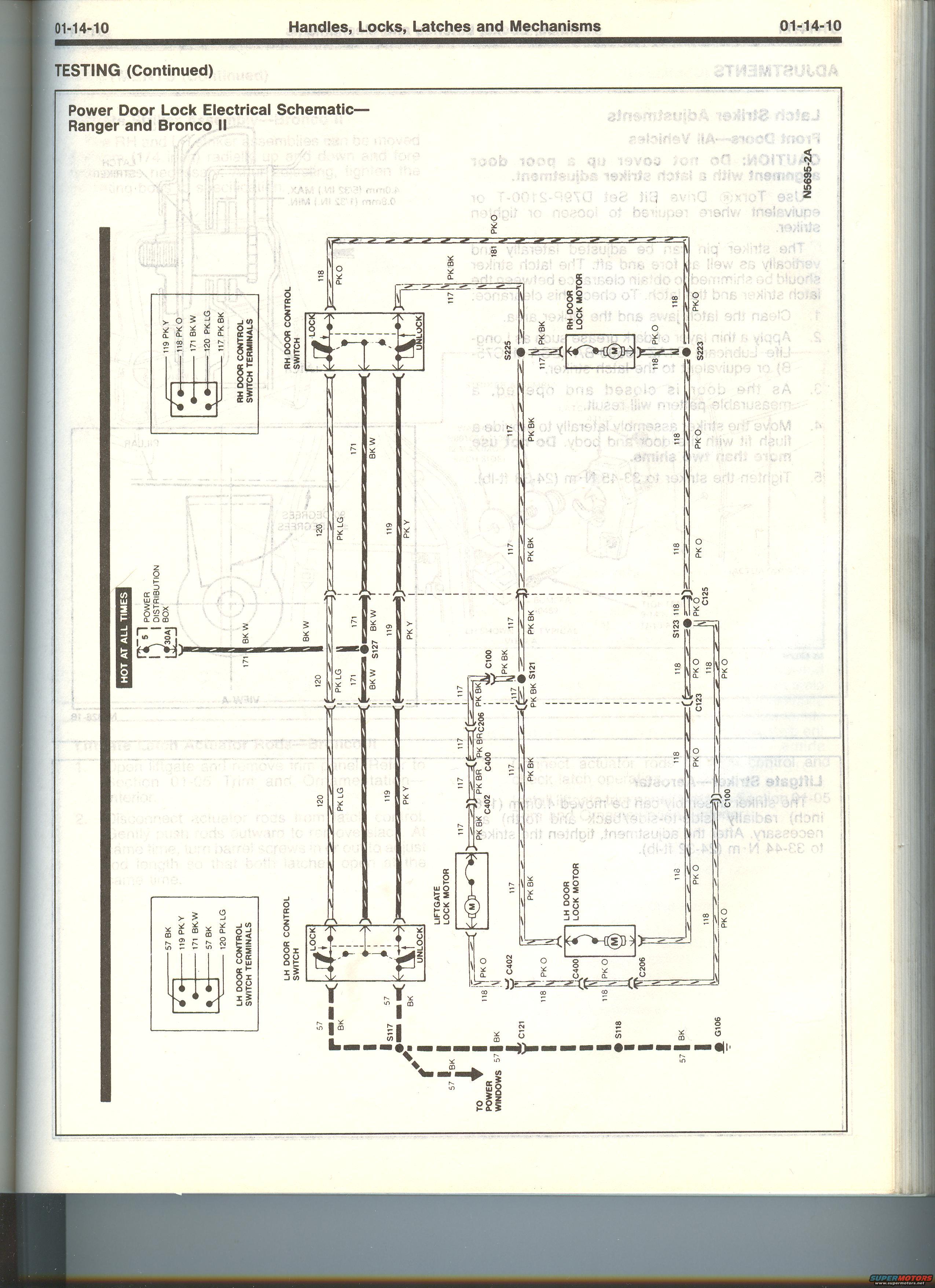
Ford Ranger & Bronco II Power Door Lock Wiring Diagram - Factory Schematic
Reference · 1983-1992 RangerAll 4 wiring diagrams
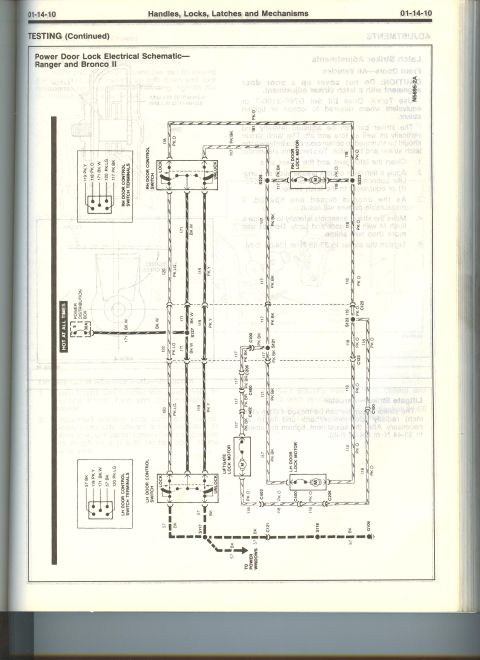
Wiring diagram of the power door lock electrical circuit for Ranger and Bronco II showing motors, controls and color-coded wires.
Part of 1983-1992 Ford Ranger Wiring Diagrams
This is a scanned page (01-14-10) from a Ford factory service manual section titled 'Handles, Locks, Latches and Mechanisms, TESTING (Continued)'. It presents the Power Door Lock Electrical Schematic for the Ford Ranger and Bronco II (diagram N5695-2A). The schematic shows power originating from fuse 5 (30A) in the Power Distribution Box (hot at all times) on circuit 171 (BK/W), feeding the RH and LH door control switches. Lock and unlock signals travel on circuits 118 (PK/O) and 117 (PK/BK, shown as PK/BR in part of the liftgate run) to the RH door lock motor, LH door lock motor, and liftgate lock motor. Circuits 119 (PK/Y) and 120 (PK/LG) interconnect the two door control switches, and circuit 57 (BK) provides the ground path through splices S117 and S118 to ground G106, with a branch labeled 'To Power Windows'. Legend boxes identify the terminal pinouts for both the RH and LH door control switches. Connectors C100, C121, C123, C125, C206, C400 and C402, plus splices S121, S123, S127, S223 and S225, are labeled. A reader can use this page to diagnose power door lock circuits, trace wire colors/circuit numbers, and identify switch terminals on a Ranger or Bronco II.
Is this accurate? Sign in to help verify it.
Frequently asked questions
- What fuse powers the power door locks on the Ford Ranger and Bronco II?
- The schematic shows the door lock circuit is fed from fuse 5, a 30A fuse in the Power Distribution Box, which is hot at all times, via circuit 171 (BK/W).
- What wire colors are used in the Ranger/Bronco II power door lock circuit?
- Circuit 171 is BK/W (power feed), 118 is PK/O (lock), 117 is PK/BK (unlock, shown as PK/BR in part of the liftgate run), 119 is PK/Y, 120 is PK/LG, 181 is PK/O, and 57 is BK (ground).
- What are the terminal wires at the RH door control switch?
- The legend shows the RH door control switch terminals as: 119 PK Y, 118 PK O, 171 BK W, 120 PK LG, and 117 PK BK.
- Where does the door lock circuit ground?
- Circuit 57 (BK) from the LH door control switch runs through splice S117, connector C121, and splice S118 to ground G106; a branch from S117 also goes 'To Power Windows'.
- Does this diagram include the liftgate lock?
- Yes, a liftgate lock motor is shown, wired on circuits 118 PK/O and 117 PK/BK (PK/BR) through connectors C206, C400, and C402.
No comments yet.