Diagram of 1992-96 Ford starter and battery wiring with labeled…
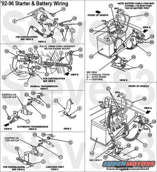
'92-96 Battery & V8 Starter Wiring
IF THE IMAGE IS TOO SMALL, click it.
1 Cable Assembly 14B060
2 Cable Assembly (Lightning) 14B060
3 To Heated Oxygen Sensor for 5.0L/5.8L Under 8500, 5.8L (Lightning), and 7.5L F-450 Only
4 Bolt 56558-S 26-34 N-m (19-25 Ft-Lb)
5 Starter Motor 11002 (E9SZ11002BRM SA769ARM with auto trans; F2TZ11002ARM SA793RM with manual trans)
6 Nut and Washer Assembly N805403-S100 10-14 N-m (8-10 Ft-Lb)
7 Screw and Washer Assembly 390926-S36 for All Gas, Except 7.5L Manual Transmission which use Screw 389883-S36 19-26 N-m (14-20 Ft-Lb)
8 Starter Motor Relay Assembly 11450 MotorCraft SW1951C (E9TZ-11450-B)
9 Nut and Washer Assembly 381561-S36 7-9 N-m (60-82 In-Lb)
10 Screw N803991-S36 4-6 N-m (35-49 In-Lb)
11 Cap 14A396
12 Star Washer 34943-S36
13 Existing Gas Vapor Tube 9S286
14 Battery 10655 (BXT-65-850)
15 Nut 33799-S2 (Auto Transmission) 11-16 N-m (8-12 Ft-Lb)
16 Cover-Starter Solenoid (Red) 11N087
17 Stud N806925-S36MG
18 Chassis Ground 14301 Motorcraft F2TZ-14301-B Negative Battery Cable with body, frame, & block grounds
19 Bolt for 14301 Frame Ground 390158-S36 11-16 N-m (8-12 Ft-Lb)
20 Heated Oxygen Sensor Wire Assembly 9F472
21 Exhaust Pipe 5A212
22 Wire Assembly 12A690
23 Starter Solenoid Heat Shield (5.0L/5.8L Only) (Part of 11002)
24 Frame 5005
25 To Engine Ground 14301
26 Nut N621906-S36
27 Body Grounds 12A581
28 Engine Block 6010
29 Engine Bay Harness to Power Distribution Center 12A581
30 Alternator Harness 14305
POS = heavy Red circuit from battery Positive to starter relay, starter solenoid, alternator, and power distribution center
NEG = heavy Black circuit from battery Negative to frame, block, and fender
SOL = medium Red circuit from starter relay to starter solenoid
See also: .
.  .
.  .
.  .
.  .
.  .
.  .
.  .
.  .
.  .
.  .
.  .
.  .
.  .
.  .
.  .
. 
https://www.fleet.ford.com/truckbbas/non-html/1997/c37_39_p.pdf
___________________________________________________
"Grounding" is commonly misunderstood...
When electricity first became publicly available (when Edison & Tesla were fighting over DC vs. AC), Copper wire was very expensive. So rather than run 2 wires everywhere, Tesla realized he could run a "hot" wire, and then use the ground (the actual dirt of the Earth) as the return circuit path. (He also thought he could use the ionosphere as the hot side, but he never got that to work.) Inside a house, there still had to be 2 wires, but one of them went "to the ground" via a Copper rod driven into the dirt outside the house. That became known as "the ground wire". When vehicles acquired electric circuits (AFAIK, the first on any Ford was the electric horn, which Ford always numbers as circuit #1), it was equally-efficient to use the metal chassis of the vehicle as one the main electrical pathway, to reduce the amount of wire needed. And the term "ground" was carried over into that arena. Chassis grounding worked reasonably-well until alternators got up into the ~100A range (in the 80s) and vehicle wiring harnesses began to exceed the weight of the drivetrain (AFAIK, the first to cross that line was the '92 Lincoln Continental V6). Since then, more circuits are networked through high-speed data bus lines via communication modules so that you don't need a discrete wire running from one end of the vehicle to the other & another coming back to turn on a taillight, and confirm that the bulb isn't burnt out.
But as a result, the chassis/body ground is no longer sufficient to provide a reliable circuit path without introducing a lot of background noise (RFI) into those minuscule high-frequency data signals. So the trend for a couple of decades now has been to run actual Copper return wires so that far less current flows through the chassis steel. (House wiring standards added a return "neutral" wire decades before that.)
So by definition, if you're using a wire to return to the battery, you're not "grounding" that circuit - you're wiring it. And wiring it is a good idea when you're dealing with rusty 40- to 50-year-old body & frame steel. The catch is that the return wiring has to be AT LEAST as large as ALL the power wiring that it serves - IOW, very big like the alternator output wire, the starter wire, the winch wiring, and the ignition switch battery-supply wires. None of it needs to be bigger than the battery cables because you can't ever get more current flowing than the battery can put out (roughly whatever its CA rating is).
So if you want to be sure you have a good return path throughout any vehicle, just extend the battery (-) cable all the way to the trailer connector. Obviously, you can't run a cable that big into the trailer connector or anything else - you have to splice onto it to branch off with smaller black wire (or whatever color the particular circuit uses for "ground"). That's why I refer to that as a "trunk ground" system - the main return wire is like a big tree trunk, with the variously-sized smaller branches shooting out to hit each point on the vehicle that needs an exceptionally-reliable return (generally: the high-current devices; and those that require low RFI noise, like audio amplifiers).
Fortunately, those splices DON'T need to be insulated - they can be left showing bare metal. Copper & solder don't corrode very quickly in air, or even in common rainwater. Mainly just at the battery where acid leaks out. Road salt will eventually cause some corrosion, but probably not enough to matter within the remaining lifespan of even the best-maintained antiques.
And the body & frame should still be GROUNDED at a few points, just to reduce galvanic corrosion, and to serve the very-low-current chassis-grounded loads like taillights & fuel level senders.
Is this accurate? Sign in to help verify it.
Comments
More from this build


No comments yet.