Home/
Registry/
Ford/
Ranchero/
1972-1976/
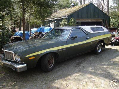
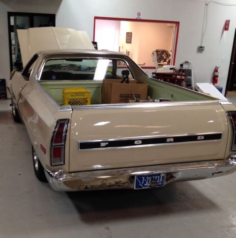
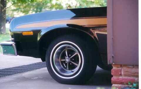
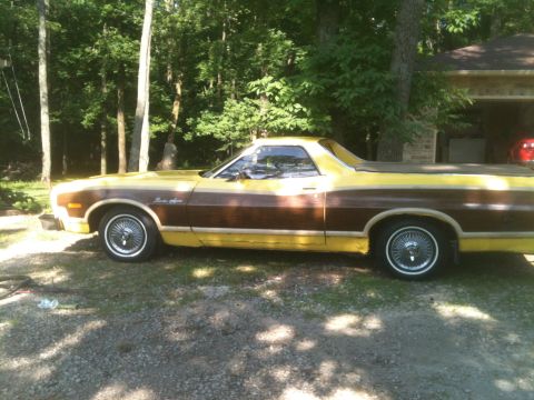
1972 Ford Ranchero/
Photo
supermotors.net/registry/media/842881
1967-72 Ford, Thunderbird & Torino Air Leveler Rear Suspension Parts Diagram

Reference · 1972-1976 RancheroAll 26 exploded parts diagrams


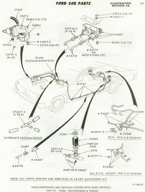

Ford Car Parts illustration (Section 54): exploded view of the rear-suspension air-leveler system with dash control, listing vacuum manifold 9C490 and part-of-5560 components serviced in 5A589 accessory kit for 1967-72 Ford, Thunderbird and Torino.
Part of 1972-1976 Ford Ranchero Exploded Parts Diagrams
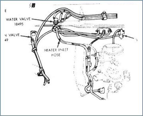
This is page 19 of Ford Car Parts, Illustration Section 54 (plate P-10678), showing an exploded parts diagram of the rear suspension air leveler system with dash control for 1967-1972 Ford, Thunderbird & Torino models. The illustration depicts the full vehicle layout with arrows connecting detail views: the air compressor/pump assembly with mounting bracket and hardware (17543, 5A713, 5A694, 2A965, 26483-S, 34825-S, 33795-S, 33797-S), the dash control valve assembly (5A687 with fittings 357940-S, 5A739 or 382215-S), vacuum manifold connection (9C490), air line routing along the frame (5703), an alternate vacuum outlet tee (374677-S), an air fitting/filter assembly (5536, 5A666, part of 5560, 352114-S), and engine-specific hose/line routings, one for the 8-cylinder 302-2/B engine and one for all 8-cylinder engines except the 302-2/B (5A667, 5A668, 5A680, 34977-S, 5A689, 5A718). A note states that all starred parts shown are serviced in the 5A589 accessory kit. Readers can identify part numbers, hardware, and routing locations for servicing or restoring the factory air leveler rear suspension option.
Is this accurate? Sign in to help verify it.
Frequently asked questions
- What vehicles does this air leveler suspension diagram cover?
- The diagram is labeled for 1967/72 Ford, Thunderbird & Torino, covering the rear suspension air leveler system with dash control.
- What kit services the parts shown in this diagram?
- A note on the page states that all parts shown are serviced in the 5A589 accessory kit.
- Are there different parts depending on the engine?
- Yes. One detail view shows line/valve routing for the 8-cylinder 302-2/B engine, and another shows the routing for all 8-cylinder engines except the 302-2/B, both using part 5A667 and hardware 34977-S.
- What is part 9C490 in this system?
- 9C490 is labeled as the vacuum manifold, which the system connects to; an alternate vacuum outlet using tee 374677-S (II-98-K) is also shown.
- What part numbers make up the dash control valve assembly?
- The control assembly detail shows 5A687 with fittings 357940-S (II-54-X), 26483-S (U-172), 33795-S (M-49), 34825-S, and hose 5A739 or 382215-S (UU-137), plus 5A718.

No comments yet.