Home/
Registry/
Ford/
Ranchero/
1972-1976/
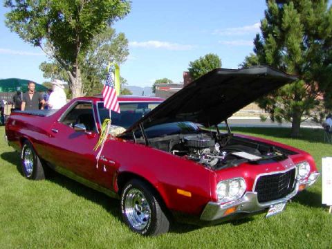
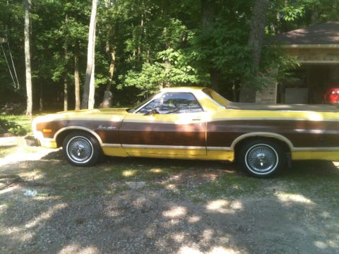
1972 Ford Ranchero/
Photo
supermotors.net/registry/media/1023290
1979 Ford Wiring Diagram: Ignition, Charging, Starting & A/C Blower Circuits

Reference · 1972-1976 RancheroAll 12 wiring diagrams
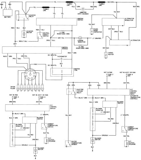
Color-coded automotive wiring diagram covering charging, ignition, spark plug and A/C control circuits.
Part of 1972-1976 Ford Ranchero Wiring Diagrams
This scanned wiring diagram covers two major systems of a Ford vehicle (uploaded as "1979 Wiring"). The upper half shows the starting, charging, and ignition circuits: battery, starter relay, starter motor, three fusible links, ignition switch, neutral safety switch, ignition module, ignition coil, distributor feeding eight spark plugs, tachometer, ammeter (with gauges), charge indicator with 1.1 ohm and 15 ohm resistance wires, alternator, alternator regulator, radio noise capacitor, and choke heater. Wire colors are labeled throughout (e.g., YEL, RED/LT BLU, ORG/LT BLU, DK GRN/YEL, WHT/BLK, BLK/ORG). The lower half shows two A/C-heater blower circuits: a standard A/C control switch version and a version with automatic temperature control including an electric vacuum relay and water temperature sender. Both A/C circuits are fed by Fuse 2 (35A, hot in run) and Fuse 8 (20A, hot in accessory or run), and include the blower switch, blower resistor, blower motor, ambient temperature switch, and A/C clutch solenoid, with color codes such as BRN/ORG, WHT/PPL, BLU/LT GRN, LT GRN/PPL, YEL/RED, and ORG/BLK. A reader can trace power flow, fuse feeds, wire colors, and component connections for diagnosing starting, charging, ignition, and A/C blower problems.
Is this accurate? Sign in to help verify it.
Frequently asked questions
- What fuses power the A/C system in this diagram?
- Fuse 2 (35A, hot in run, BRN/ORG wire) and Fuse 8 (20A, hot in accessory or run, WHT/PPL wire) feed the A/C control switch circuits.
- What wire colors connect to the ignition module?
- The diagram shows WHT, RED/LT BLU, ORG/LT BLU, BLK/LT GRN, PPL/LT BLU, ORG/YEL, DK GRN/YEL, and RED/LT GRN wires at the ignition module.
- What resistance wires are in the charging indicator circuit?
- A 1.1 ohm resistance wire (GRY/YEL) and a 15 ohm resistance wire connect to the charge indicator circuit.
- What color wire runs from the blower resistor to the blower motor?
- ORG/BLK feeds the blower motor, which grounds through a BLK wire.
- How many fusible links are shown?
- Three fusible links are shown: one on a YEL wire near the starter relay/ignition feed, one before the ammeter (YEL to YEL/LT GRN), and one between RED/ORG and BLK/ORG.

No comments yet.