Home/
Registry/
Ford/
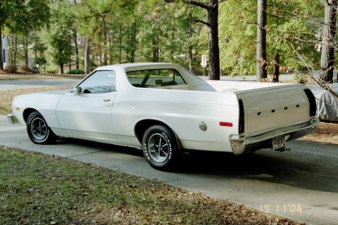
Ranchero/
1972-1976/
“Uwe der Auto”/
Photo
supermotors.net/registry/media/888516
RM7 Veerlink 190mm Link Plate Blueprint - Linkbrug CAD Drawing Dimensions

Dimensioned engineering blueprint of a suspension link bracket with a title block, with the actual machined part laid on the print.
This document is a CAD engineering drawing (dated September 2006) for a suspension link plate, titled "RM7 Veerlink 190mm inbouw" (Dutch for "RM7 shock link, 190mm installed length"), with the part name "linkbrug" (link bridge). It shows two link plate designs identified by callout balloons 1 and 2, each drawn in top and side views, with an isometric rendering of the finished part at the top of the sheet. Key dimensions on the main plate include an overall length of 135 mm, hole spacings of 55 mm and 112 mm, vertical dimensions of 45 mm and 68 mm, plate thicknesses of 5 mm and 12 mm, an R11 radius, and Ø8 mm holes. The title block credits Jorg Moolenaar as designer, T.Derks as checker, with approval dated 18-09-2006 and a drawing date of 14-9-2006. A physical machined black link plate is photographed lying on top of the drawing for comparison. Handwritten notes ("autocad", "tangens", "Radius") mark up the sheet. Despite being filed under a 1973 Ford Ranchero, this is a mountain bike suspension linkage drawing (Rocky Mountain RM7), not an automotive document.
This document covers 2006, which may differ from this 1973 Ford Ranchero.
Is this accurate? Sign in to help verify it.
Frequently asked questions
- What part does this blueprint show?
- It shows a link plate ("linkbrug") titled "RM7 Veerlink 190mm inbouw", drawn in top, side, and isometric views, with a machined example of the part photographed on the drawing.
- What are the main dimensions of the link plate?
- Overall length 135 mm, hole spacings of 55 mm and 112 mm, vertical dimensions of 45 mm and 68 mm, thicknesses of 5 mm and 12 mm, an R11 radius, and Ø8 mm holes.
- Who designed and checked this drawing, and when?
- It was designed by Jorg Moolenaar, checked by T.Derks, dated 14-9-2006, with approval dated 18-09-2006.
- How many parts are detailed on the sheet?
- Two link plate designs are shown, identified by callout balloons 1 and 2, on Sheet 1/1.
Comments
More from this build

No comments yet.