Home/
Registry/
Ford/
Ranchero/
1972-1976/
1972 Ford Ranchero/
Photo
supermotors.net/registry/media/1011797
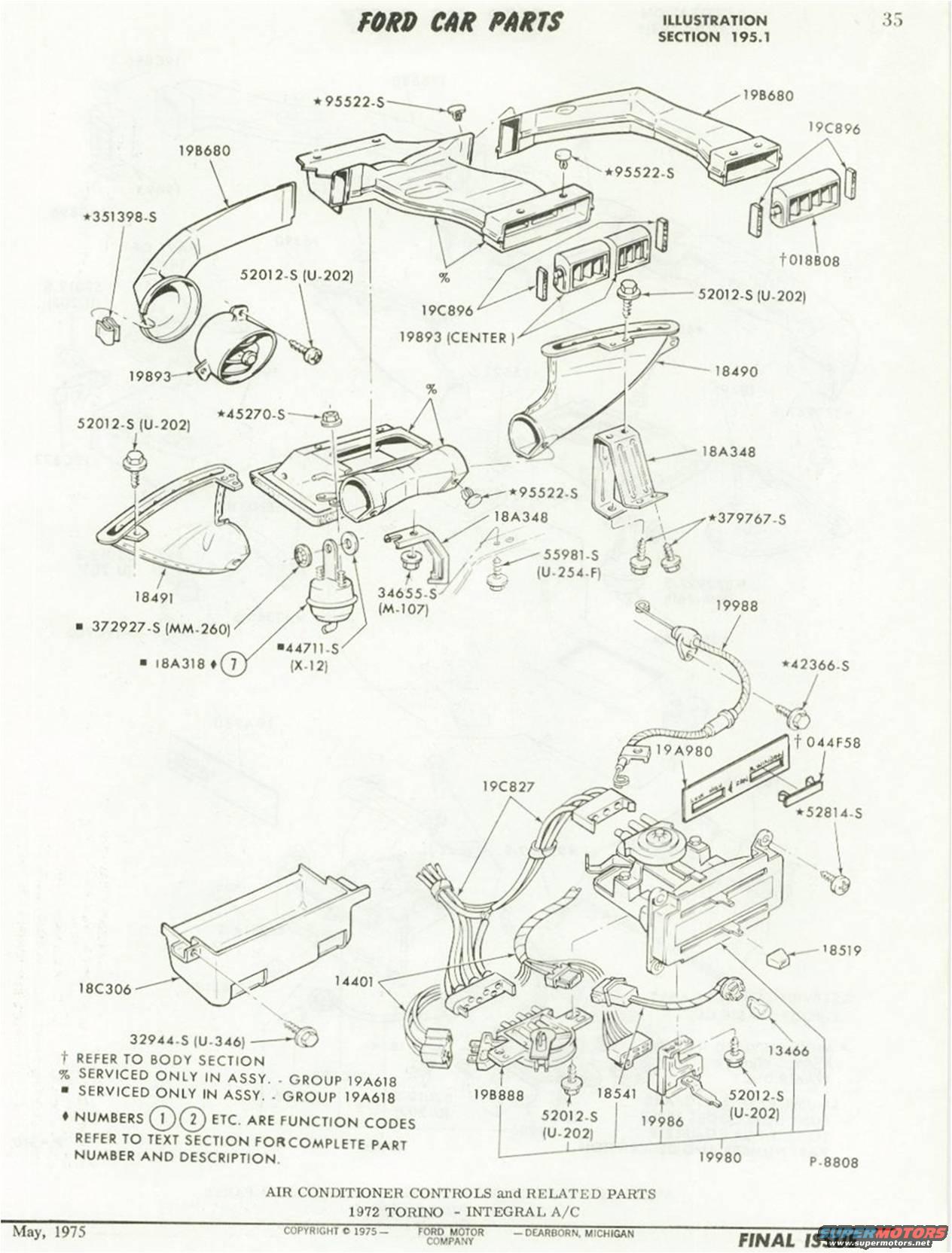
1972 Ford Torino Integral A/C Controls Exploded Parts Diagram - Ford Car Parts
Reference · 1972-1976 RancheroAll 26 exploded parts diagrams


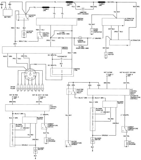
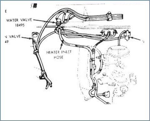
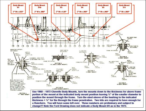
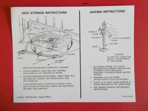
Ford car parts illustration of 1972 Torino integral air conditioner controls, ducts and components with part numbers.
Part of 1972-1976 Ford Ranchero Exploded Parts Diagrams
This is page 35 from the Ford Car Parts illustration catalog, Section 195.1, dated May 1975 (marked "FINAL ISSUE," Copyright 1975 Ford Motor Company, Dearborn, Michigan). It presents an exploded parts diagram of the air conditioner controls and related parts for the 1972 Torino with integral (factory) A/C. The illustration (drawing number P-8808) shows dashboard A/C ducting (19B680), registers/louvers (19C896, 19893, 018B08), duct brackets (18A348, 18490, 18491), the control assembly and cables (19980, 19986, 19988, 19B888, 18541, 13466), wiring harness (14401, 19C827, 19A980), control face plate items (044F58, 18519), a glove-box style housing (18C306), and numerous fasteners such as 95522-S, 52012-S (U-202), 351398-S, 45270-S, 379767-S, 55981-S (U-254-F), 34655-S (M-107), 372927-S (MM-260), 44711-S (X-12), 32944-S (U-346), 42366-S, and 52814-S. A legend explains symbols: † parts are covered in the body section, % and ■ parts are serviced only in assembly under group 19A618, and ♦ numbers are function codes referencing the text section for complete part numbers and descriptions. Readers can identify basic part numbers and assembly relationships for restoring or repairing the integral A/C control system.
Is this accurate? Sign in to help verify it.
Frequently asked questions
- What vehicle and system does this diagram cover?
- It covers the Air Conditioner Controls and Related Parts for the 1972 Torino with integral A/C, from Ford Car Parts Illustration Section 195.1.
- What is the basic part number for the A/C control assembly wiring harness shown?
- The wiring harness callouts shown are 14401 and 19C827, with 19A980 also labeled near the control cable area.
- What do the % and ■ symbols mean on this page?
- Both indicate parts serviced only in assembly under group 19A618.
- What does the † symbol mean?
- † means refer to the Body Section (used for parts 018B08 and 044F58).
- When was this catalog page published?
- May 1975, copyright 1975 Ford Motor Company, marked as the Final Issue.

No comments yet.