Home/
Registry/
Hyundai/
Genesis Coupe/
2010-2016/
“Coupe”/
Photo
supermotors.net/registry/media/1023810
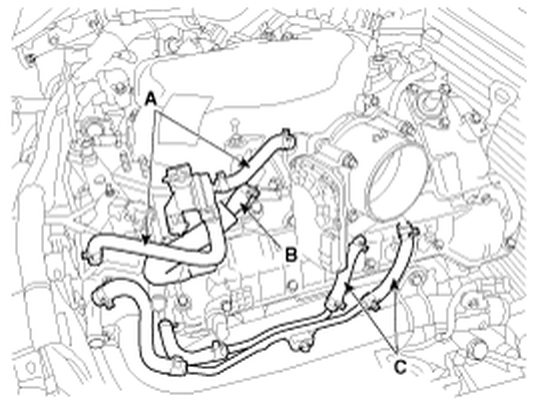
2010 Hyundai Genesis 3.8L V6 Throttle Body Coolant Hose Routing Diagram
Reference · 2010-2016 Genesis CoupeAll 3 vacuum routing diagrams

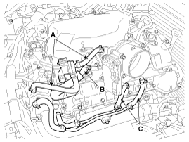
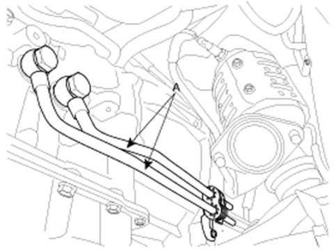








Line-drawing routing diagram of engine hoses around the intake and throttle body identified by callouts A, B and C.
Part of 2010-2016 Hyundai Genesis Coupe Vacuum Routing Diagrams
This document is a black-and-white line illustration from a service manual showing the routing of coolant hoses in the vicinity of the throttle body on a V6 engine (uploader identifies it as the 3.8L engine in a 2010 Hyundai Genesis). The drawing depicts the engine bay from above, with the intake manifold and throttle body visible on the right side. Three callout labels identify hose groups: label "A" (with two arrows) marks two upper coolant hoses that route over the intake manifold to the throttle body area; label "B" marks a hose connection or fitting near the center of the engine; and label "C" (with two arrows) marks two lower coolant hoses routed along the lower right side toward the throttle body. No legend, part numbers, torque specifications, or descriptive text accompany the labels in this scan, so the reader must consult the companion page or service manual text to identify components A, B, and C by name. The illustration is useful for visually confirming correct hose routing and connection points when servicing, replacing, or reinstalling throttle body coolant hoses.
Is this accurate? Sign in to help verify it.
Frequently asked questions
- What does this diagram show?
- It is a line illustration of coolant hose routing around the throttle body area of a V6 engine, with three callout labels (A, B, and C) marking hose groups and a connection point.
- How many hose locations are labeled in the diagram?
- Three labels are shown: A (pointing to two upper hoses), B (pointing to a central connection/fitting), and C (pointing to two lower hoses near the throttle body).
- Does the diagram include a legend identifying parts A, B, and C?
- No. Only the letter callouts A, B, and C are visible; no legend, part names, or part numbers appear on this page.
- Are any torque specs or part numbers given?
- No. The scan contains no torque values, part numbers, or written instructions, only the labeled illustration.

No comments yet.