Home/
Registry/
Hyundai/
Genesis Coupe/
2010-2016/
“Coupe”/
Photo
supermotors.net/registry/media/1154794
Hyundai Genesis Coupe BK Power Steering Pump Disassembly - Steering ST-20
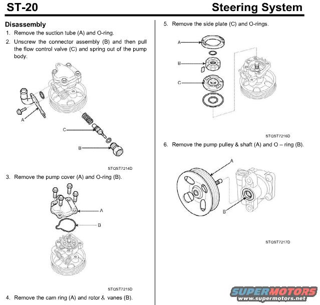
Reference · 2010-2016 Genesis CoupeAll 14 exploded parts diagrams

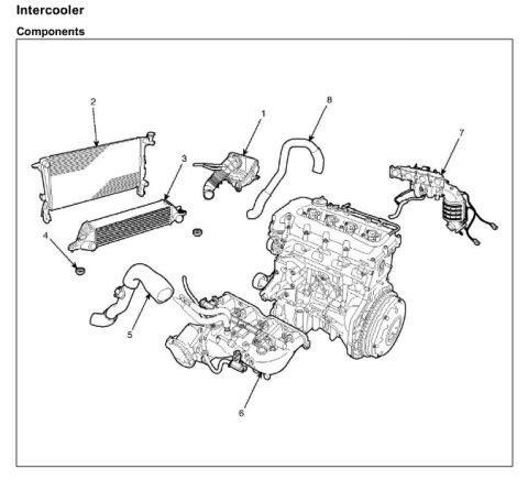
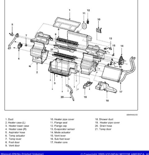
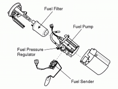








Power steering pump disassembly procedure with exploded views of the flow control valve, cover, cam ring and pulley.
Part of 2010-2016 Hyundai Genesis Coupe Exploded Parts Diagrams
This is page ST-20 from a Steering System service manual section, covering the disassembly procedure for a power steering pump. The page presents six numbered steps with accompanying exploded-view illustrations: (1) removing the suction tube (A) and O-ring; (2) unscrewing the connector assembly (B) and pulling out the flow control valve (C) and spring from the pump body; (3) removing the pump cover (A) and O-ring (B); (4) removing the cam ring (A) and rotor & vanes (B); (5) removing the side plate (C) and O-rings; and (6) removing the pump pulley & shaft (A) and O-ring (B). Each step's illustration is labeled with callout letters matching the text and carries figure reference codes STQST7214D, STQST7215D, STQST7216D, and STQST7217D. A reader can learn the correct order for tearing down this vane-type power steering pump and identify the major internal components, flow control valve, cam ring, rotor and vanes, side plate, and pulley/shaft assembly. No torque values, part numbers, or vehicle year/model information appears on this page.
Is this accurate? Sign in to help verify it.
Frequently asked questions
- What is the first step to disassemble the power steering pump?
- Remove the suction tube (A) and O-ring, then unscrew the connector assembly (B) and pull the flow control valve (C) and spring out of the pump body.
- How do you remove the flow control valve from the pump?
- Unscrew the connector assembly (B) and then pull the flow control valve (C) and spring out of the pump body.
- What internal components are removed after the pump cover?
- After removing the pump cover (A) and O-ring (B), remove the cam ring (A), rotor & vanes (B), then the side plate (C) and O-rings.
- What is the last step of the pump disassembly?
- Step 6: remove the pump pulley & shaft (A) and O-ring (B).

No comments yet.