Home/
Registry/
Hyundai/
Genesis Coupe/
2010-2016/
“Coupe”/
Photo
supermotors.net/registry/media/1170831
2010 Hyundai Genesis Coupe Smart Key System Connector Pinouts (SD815-4)
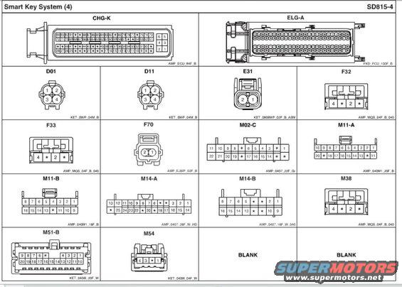
Connector identification page for a Smart Key System showing connector views and terminal numbering.
Part of 2010-2016 Hyundai Genesis Coupe Schematics
This document is page SD815-4, titled 'Smart Key System (4)', a connector pinout reference sheet from a Hyundai service schematic set. It shows face-view drawings of the electrical connectors used in the smart key (push-button start) system, each with its connector designation, cavity/pin numbering layout, and the connector housing part specification. Connectors depicted include the large CHG-K 94-pin ECU connector (AMP_ECU_94F_B), the ELG-A 100-pin PCU connector (PKD_PCU_100F_B), and smaller connectors D01, D11 (4-pin KET_SWP_04M_B), E31 (2-pin KET_090IIWP_02F_B_ASM), F32, F33, M38 (4-pin AMP_MQS_04F_B_040), F70 (2-pin AMP_EJWP_02F_B), M02-C (22-pin AMP_0407_22F_Gr), M11-A (20-pin AMP_040M1_20F_B), M11-B (16-pin AMP_040M1_16F_B), M14-A (26-pin AMP_0407_26F_W_HD), M14-B (16-pin AMP_0407_16F_W_040), M51-B (20-pin KET_040III_20F_W), and M54 (4-pin KET_040III_04F_W). Two cells are marked BLANK. Asterisks in the pin grids indicate unused/unlabeled cavities. A technician can use this page to identify connector shapes, pin orientation, and cavity numbering when probing or repairing smart key system wiring, in conjunction with the related wiring diagram pages in the same album (BK1 Genesis Coupe set).
Is this accurate? Sign in to help verify it.
Frequently asked questions
- What connectors are shown on the Smart Key System (4) page SD815-4?
- CHG-K (AMP_ECU_94F_B), ELG-A (PKD_PCU_100F_B), D01 and D11 (KET_SWP_04M_B), E31 (KET_090IIWP_02F_B_ASM), F32/F33/M38 (AMP_MQS_04F_B_040), F70 (AMP_EJWP_02F_B), M02-C (AMP_0407_22F_Gr), M11-A (AMP_040M1_20F_B), M11-B (AMP_040M1_16F_B), M14-A (AMP_0407_26F_W_HD), M14-B (AMP_0407_16F_W_040), M51-B (KET_040III_20F_W) and M54 (KET_040III_04F_W).
- How many pins does the CHG-K smart key ECU connector have?
- CHG-K is a 94-position connector (AMP_ECU_94F_B) with pins numbered up to 94; several positions are shown as unused (marked *).
- What is the pin numbering of connector M11-A?
- M11-A (AMP_040M1_20F_B) is a 20-position connector: top row 10 9 8 7 6 5 4 3 2 1, bottom row 20 * 18 17 16 15 14 13 * 11, where * indicates unused cavities.
- What connector housing is used for E31?
- E31 is a 2-pin connector (pins 2 and 1) with housing designation KET_090IIWP_02F_B_ASM.
- What do the asterisks (*) in the connector pin diagrams mean?
- Asterisks mark cavity positions that are shown without pin numbers, i.e., unused/unpopulated positions in the connector.
Comments
More from this build









No comments yet.