Ford HO2S #3/#4, IAT & Octane Adjust Wiring Diagram - PCM Pinout (4R70W)
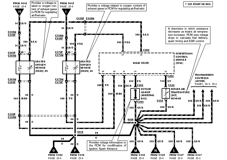
Wiring diagram of heated oxygen sensors 3 and 4, octane adjust and intake air temperature sensor circuits to the PCM with color codes.
This document is one page (E5) of a multi-page Ford factory-style wiring diagram set covering the engine control / EEC system. It shows the wiring for Heated Oxygen Sensors (HO2S) #3 and #4, the Powertrain Control Module (PCM, labeled SOLID STATE), the Intake Air Temperature (IAT) sensor, and the Octane Adjust shorting bar. Power for the oxygen sensor heaters comes from S142 on circuit 34 LB/O (12V in START or RUN), with sensor signal wires 392 R/LG and 393 P/LG feeding the PCM, signal returns 390 T/Y and 389 W/BK, and ground circuit 89 O through splice S113. The IAT sensor connects to PCM pin 33 via circuit 743 GY and returns on 359 GY/R through splice S166, which also serves the octane adjust circuit (242 DG at PCM pin 30) and multiple transmission control branches for the 4R70W transmission (referenced to pages 30-1 and 30-2). Connectors identified include C116M/C116F, C181F/C181M, C173F/C173M, C202, C103, C155, C110, C159, C157, C147, C182, and C116. Explanatory callouts describe how the O2 sensors regulate air/fuel ratio, how the IAT thermistor affects fuel delivery, spark timing and EGR, and how the octane adjust bar modifies ignition spark advance. A reader can trace wire colors, circuit numbers, PCM pin numbers, and splice locations for diagnosis.
Is this accurate? Sign in to help verify it.
Frequently asked questions
- What wire color and circuit feeds power to the heated oxygen sensors?
- Circuit 34 LB/O (light blue/orange) from splice S142, which is 12V in START or RUN, powers both HO2S #3 and HO2S #4 heaters.
- What PCM pin does the IAT sensor connect to?
- The IAT sensor signal goes to PCM pin 33 on circuit 743 GY through connector C202, with its return on circuit 359 GY/R to splice S166.
- What does the octane adjust shorting bar do?
- Per the diagram callout, it provides voltage information to the PCM for modification of Ignition Spark Advance; it connects to PCM pin 30 via circuit 242 DG through connector C103.
- Which wires carry the oxygen sensor signals to the PCM?
- HO2S #3 uses circuit 392 R/LG and HO2S #4 uses circuit 393 P/LG for signal, with returns 390 T/Y (PCM pin 96) and 389 W/BK (PCM pin 95).
- What transmission does this diagram reference?
- The 4R70W transmission — transmission controls are cross-referenced to pages 30-1 and 30-2, with three 359 GY/R sensor return branches tied to splice S166.
Comments
More from this build






No comments yet.