Ford PCM Wiring Diagram – 4R70W Trans Controls, CMP Sensor, MIL/TCIL Circuits
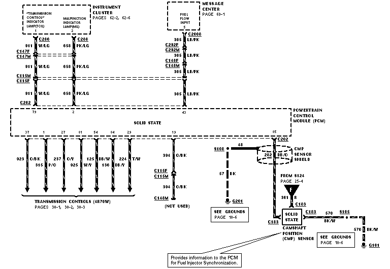
Wiring diagram of instrument cluster, transmission controls and camshaft position sensor circuits to the PCM with color codes.
This document is a single page from a Ford factory-style wiring diagram (EVTM) showing Powertrain Control Module (PCM) circuits. It illustrates wiring from the PCM to the instrument cluster's Transmission Control Indicator Lamp (TCIL, circuit 911 W/LG, PCM pin 79) and Malfunction Indicator Lamp (MIL, circuit 658 PK/LG, PCM pin 2), routed through connectors C288, C147F/C147M, C115M/C115F, and C202. A Fuel Flow Input circuit (305 LB/PK) runs from the message center (C2008) through C292F/C292M and C148F/C148M to PCM pin 43. Eight PCM outputs (pins 37, 1, 27, 81, 54, 84, 29) with circuits 923 O/BK, 315 P/O, 237 O/Y, 925 W/Y, 125 W/V, 138 DB/W, 224 DB/O and 224 T/W feed the 4R70W transmission controls (pages 30-1 to 30-3). PCM pin 13 (394 O/BK) goes to C148M and is marked NOT USED. Pin 85 connects via circuit 48 to the Camshaft Position (CMP) sensor with a shield (282 DB/O), grounds at G201 and G101 via circuits 57 BK and 570 BK/W, and power feed 361 R from S124. A note states the CMP sensor provides information to the PCM for fuel injector synchronization.
Is this accurate? Sign in to help verify it.
Frequently asked questions
- Which PCM pin connects to the Malfunction Indicator Lamp (MIL)?
- PCM pin 2 at connector C202, using circuit 658 PK/LG routed through connectors C115M/C115F, C147F/C147M, and C288 to the instrument cluster MIL.
- What wire color and circuit number is the Transmission Control Indicator Lamp (TCIL)?
- Circuit 911, white/light green (W/LG), from PCM pin 79 through C202, C115M/C115F, C147F/C147M and C288 to the instrument cluster.
- What does the Camshaft Position (CMP) sensor do according to this diagram?
- A callout states it 'Provides information to the PCM for Fuel Injector Synchronization.' It connects to PCM pin 85 via circuit 48, with a shield (282 DB/O) grounded through 57 BK to G201, power from S124 on circuit 361 R, and ground via 570 BK/W to G101.
- Which PCM pins control the 4R70W transmission?
- Pins 37 (923 O/BK), 1 (315 P/O), 27 (237 O/Y), 81 (925 W/Y), 54 (125 W/V), 84 (138 DB/W), and 29 (224 DB/O / 224 T/W), covered on pages 30-1, 30-2, and 30-3.
- What is the Fuel Flow Input circuit to the PCM?
- Circuit 305 LB/PK from the message center (connector C2008, page 69-1), routed through C292F/C292M and C148F/C148M to PCM pin 43.
Comments
More from this build






No comments yet.