Ford C115 In-Line Connector Pinout - 42-Pin C115F & C115M Wire Circuit Chart
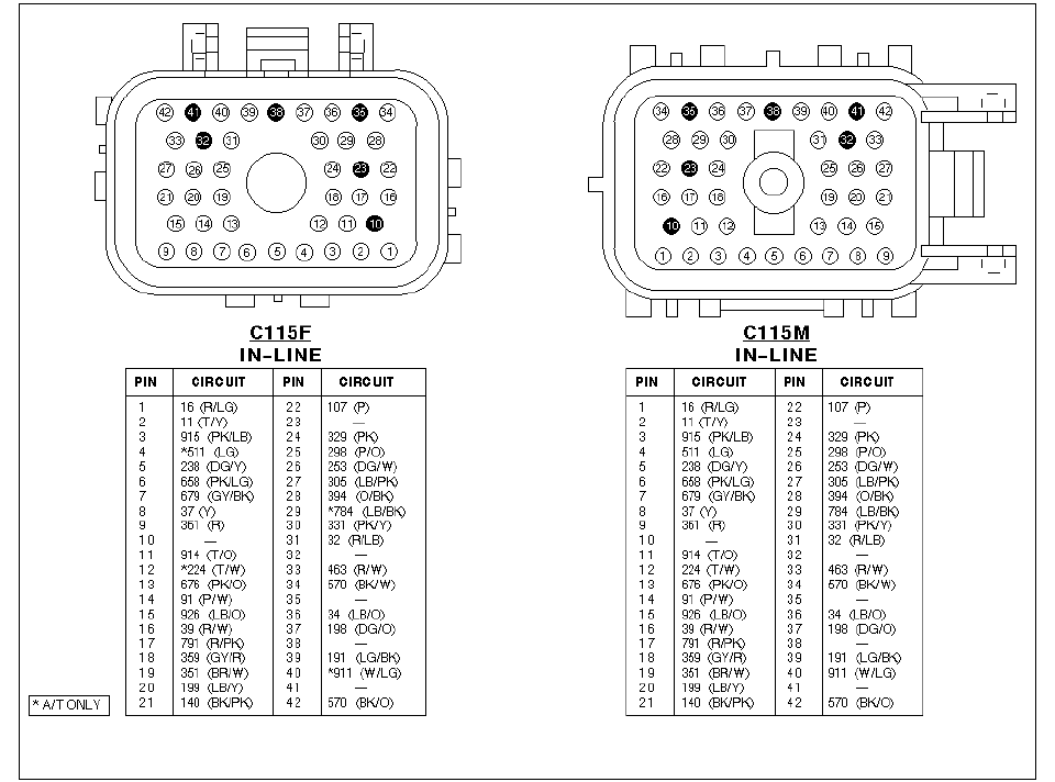
Connector face views and pin-to-circuit chart for the C115F and C115M in-line connectors listing color-coded circuits.
This document is a connector pinout reference for the C115 in-line connector pair, showing both the female (C115F) and male (C115M) 42-pin connector faces with numbered cavity diagrams, followed by pin-to-circuit tables for each side. For every pin (1–42), the tables give the Ford circuit number and wire color code, e.g. pin 1 = circuit 16 (R/LG), pin 8 = circuit 37 (Y), pin 21 = circuit 140 (BK/PK), pin 22 = circuit 107 (P), and pin 42 = circuit 570 (BK/O). Several cavities are unused, indicated by dashes (pins 10, 23, 32, 35, 38, 41). Circuits marked with an asterisk — 511 (LG) at pin 4, 224 (T/W) at pin 12, 784 (LB/BK) at pin 29, and 911 (W/LG) at pin 40 — are footnoted as applying to automatic transmission (A/T) equipped vehicles only. A reader can use this page to identify which wire (by circuit number and color) occupies each cavity of the C115 bulkhead/in-line connector, useful for tracing engine harness circuits, diagnosing broken or corroded connector pins, and repairing wiring. The document itself does not state a year, model, or engine application; it was uploaded to a 1990 Ford F-250 gallery as part of a larger wiring diagram set.
Is this accurate? Sign in to help verify it.
Frequently asked questions
- What is connector C115?
- C115 is a 42-pin in-line connector pair, shown here as C115F (female) and C115M (male), with a pin-by-pin table listing the circuit number and wire color for each cavity.
- Which pins in the C115 connector are unused?
- Pins 10, 23, 32, 35, 38, and 41 are shown with dashes in the circuit tables, indicating no circuit is assigned to those cavities.
- What do the asterisks next to some circuits mean?
- The footnote states '* A/T ONLY' — circuits *511 (LG) at pin 4, *224 (T/W) at pin 12, *784 (LB/BK) at pin 29, and *911 (W/LG) at pin 40 apply only to automatic transmission vehicles.
- What circuit is on pin 8 of the C115 connector?
- Pin 8 carries circuit 37 with a yellow (Y) wire on both the C115F and C115M sides.
- What wire color is circuit 140 on pin 21?
- Circuit 140 at pin 21 uses a black with pink stripe (BK/PK) wire.
Comments
More from this build










No comments yet.