SuperMotors SuperMotors SUPERMOTORS Search — try “orange Bronco on 35s”
Home/ Registry/ Hyundai/ Genesis/ “Coupe”/ Photo supermotors.net/registry/media/1145130

Service diagram: right side of dash panel showing M14-A and M14-…
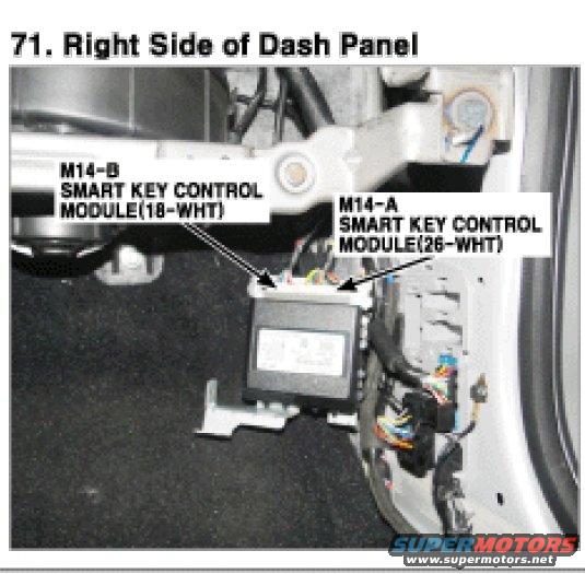
Service-manual figure 71 labeling the smart key control modules M14-A (26-WHT) and M14-B (18-WHT) at the right dash panel.

AI caption · Photo 865 of 981

Is this accurate? Sign in to help verify it.

Comments

No comments yet.

More from this build

Cooling-fan wiring diagram for Theta 2.0 TCI engine with fan relays, fuses and coolant sensor Cooling System wiring diagram for Lambda II 3.8 GDI engine with fan relays, fuses and sensor Service photo labeling instrument-panel wiring connectors I/P-A to I/P-K and Z01 diode Wiring diagram legend of wire color codes, harness and connector identification Service manual figure Photo.59 with callouts to PDM modules and rear parking assist buzzer Service manual figure labeling BCM connectors, in-car temp sensor and TPMS module Close-up of Hyundai Genesis coupe engine bay showing intake manifold, sensors, hoses, and a yellow wire. Starting system wiring diagram with battery, start relays, solenoid and motor, ignition switch and color-coded wires

More Hyundai Genesiss








