Ford 7.3L Diesel Fuel System Flow Chart - Supply, Regulator & Return Diagram

Reference · 1992-1997 F-250All 3 schematics
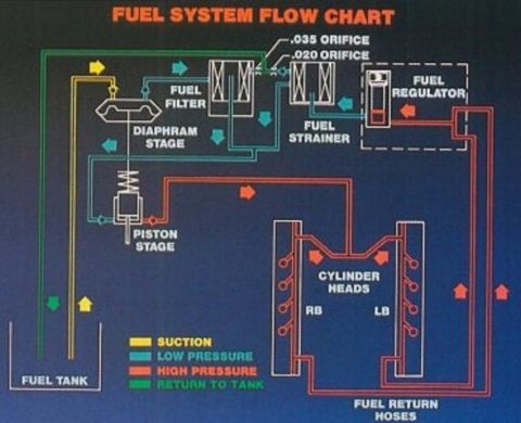
7.3L PSTD Fuel Flow Schematic
IF THE IMAGE IS TOO SMALL, click it. .
.  .
. 
Part of 1992-1997 Ford F-250 Schematics
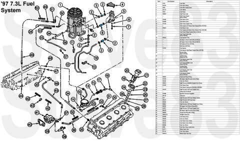
This document is a color-coded fuel system flow chart (schematic) for a diesel engine fuel supply system. It traces fuel flow beginning at the fuel tank, where it is drawn under suction (yellow) to a two-stage fuel pump depicted with a diaphragm stage and a piston stage. Low-pressure fuel (teal) passes through the fuel filter, with .035 and .020 orifices called out at the filter outlet, then through a fuel strainer to the fuel regulator (shown inside a dashed boundary). High-pressure fuel (red) is routed from the pump to the cylinder heads, labeled RB (right bank) and LB (left bank), where fuel galleries feed the injectors. Excess fuel exits via fuel return hoses and travels back to the tank on the return circuit (green). A four-row legend defines the line colors: suction, low pressure, high pressure, and return to tank. The chart lets a reader understand the complete fuel routing path, identify the sequence of filtration components (filter, strainer, orifices, regulator), distinguish supply from return plumbing, and see that both cylinder banks are fed with fuel and connected to the return system. No year, model, engine displacement, or part numbers are stated on the document itself.
Is this accurate? Sign in to help verify it.
Frequently asked questions
- What do the colored lines in this fuel system flow chart mean?
- Per the legend: yellow = suction, teal/blue-green = low pressure, red = high pressure, and green = return to tank.
- What components does fuel pass through between the pump and the cylinder heads?
- From the pump's diaphragm and piston stages, fuel goes through the fuel filter (with.035 and.020 orifices called out), the fuel strainer, and the fuel regulator; high-pressure fuel is then routed to the cylinder heads.
- What orifice sizes are shown in the diagram?
- Two orifices are labeled at the fuel filter outlet: a.035 orifice and a.020 orifice.
- What do RB and LB mean on the cylinder heads?
- They label the two cylinder heads/banks in the diagram, RB (right bank) and LB (left bank), both fed by high-pressure fuel and connected to the fuel return hoses.
- How does excess fuel get back to the tank?
- Fuel leaves the cylinder heads through the fuel return hoses and travels along the green return-to-tank line back to the fuel tank.
No comments yet.