Ford Power Stroke Diesel Lube Oil System Schematic: Oil Flow & Bypass PSI
Reference · 1992-1997 F-250All 3 schematics
7.3L Oil Systems
IF THE IMAGE IS TOO SMALL, click it.

Part of 1992-1997 Ford F-250 Schematics
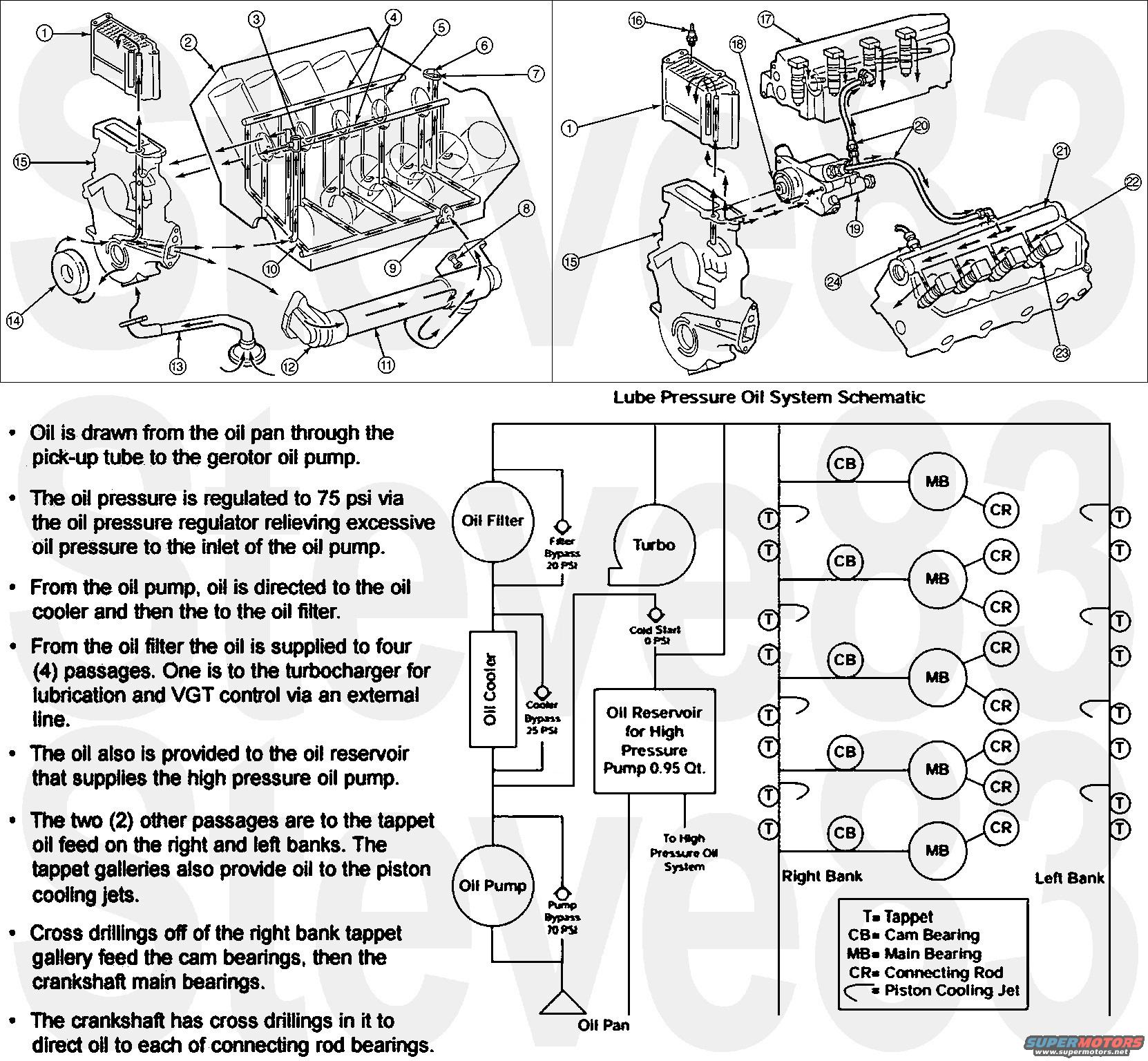
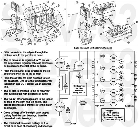
This document is a lube (low-pressure) oil system schematic and description for a Ford Power Stroke diesel engine, uploaded to a 1997 Ford F-250 gallery. The top half shows two exploded-view engine diagrams with numbered callouts (1-24) tracing oil flow through the block, oil cooler/filter housing, cylinder heads, and high-pressure oil pump area (no legend text for the numbers is included on this page). The bottom half contains a flow schematic labeled 'Lube Pressure Oil System Schematic' showing oil drawn from the oil pan through the gerotor oil pump (pump bypass 70 PSI), to the oil cooler (cooler bypass 25 PSI), then the oil filter (filter bypass 20 PSI), and on to four passages: the turbocharger (for lubrication and VGT control), the 0.95-quart oil reservoir feeding the high-pressure oil pump, and the right- and left-bank tappet galleries which also feed piston cooling jets. Cross drillings feed cam bearings, main bearings, and connecting rod bearings. Bullet text explains that oil pressure is regulated to 75 psi. A legend defines T = Tappet, CB = Cam Bearing, MB = Main Bearing, CR = Connecting Rod, and the piston cooling jet symbol. Readers learn the complete lube oil routing and bypass valve pressures for this diesel engine.
Is this accurate? Sign in to help verify it.
Frequently asked questions
- What is the regulated oil pressure in this Power Stroke lube oil system?
- Oil pressure is regulated to 75 psi via the oil pressure regulator, which relieves excessive oil pressure back to the inlet of the oil pump.
- What are the bypass valve pressures shown in the oil system schematic?
- Filter Bypass 20 PSI, Cooler Bypass 25 PSI, Pump Bypass 70 PSI, and a Cold Start valve at 0 PSI.
- How much oil does the reservoir for the high pressure oil pump hold?
- The oil reservoir for the high pressure pump holds 0.95 quart.
- Where does oil go after leaving the oil filter?
- From the oil filter, oil is supplied to four passages: one to the turbocharger for lubrication and VGT control via an external line, one to the oil reservoir supplying the high pressure oil pump, and two to the tappet oil feeds on the right and left banks (which also feed the piston cooling jets).
- What do the abbreviations T, CB, MB, and CR mean in the schematic?
- T = Tappet, CB = Cam Bearing, MB = Main Bearing, CR = Connecting Rod; a hook symbol indicates a Piston Cooling Jet.
No comments yet.