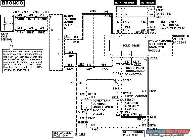
Bronco rear axle / ABS speed sensor wiring schematic with module…
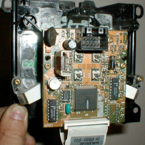
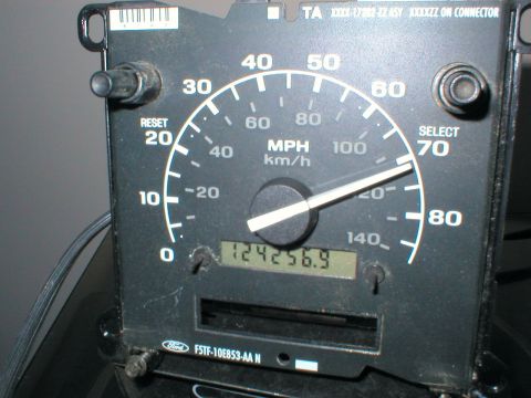
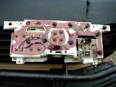
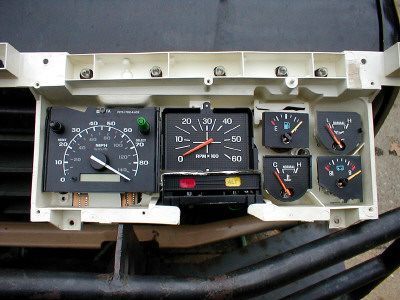
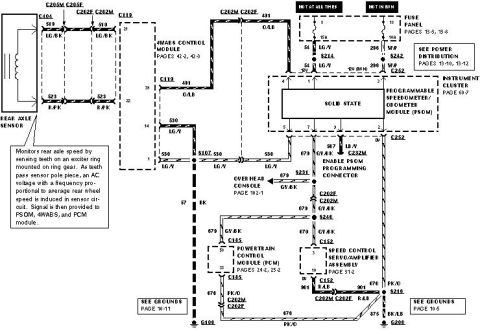
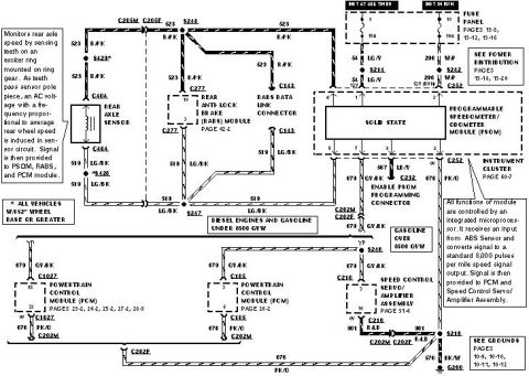
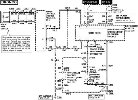
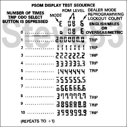
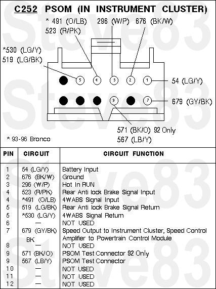
VSS 93-96 Bronco
http://www.revbase.com/BBBMotor/Wd
CHECK SPEED INPUT SIGNAL
NOTE: Only wiring harness end of connector is to be probed.
* Connect Rotunda Digital Volt-Ohmmeter 014-00407 or equivalent to Pin 4 (speed in ) and Pin 5 (speed in -).
* Does the voltage increase smoothly and continuously from 0 to approximately 3.5 volts as vehicle speed increases from 0 to 48 km/h (0 to 30 mph)?
OR:
* If available, a frequency counter may be connected to Pin 4 (Speed in ) and Pin 5 (Speed in -).
* Does the displayed frequency of the signal increase smoothly and continuously from 0 to approximately 667 Hz at approximately 48 km/h (30 mph)?
OR:
* If neither a voltmeter nor frequency counter is available, vehicle speed control may be used as a good indicator. If it works normally, then the speedometer module is at least receiving a speed input signal and the wiring and ABS sensor (DY1123, F85Z-9E731-AB) can be assumed to be good.
Rear axle sensor should read 800-1400 Ohms across the pins, and more than 10K Ohms from the metal shell to either pin
To bypass the 4WABS module & feed the ABS signal directly to the PSOM, jumper LG/Bk to LG/Y, and R/Pk to O/LB at C119. .
. 
Is this accurate? Sign in to help verify it.






No comments yet.