Home/
Registry/
Ford/
Bronco/
1980-1986/
“That dirty old truck”/
Photo
supermotors.net/registry/media/1169406
Ford Bronco 4WABS Anti-Lock Brake Wiring Diagram - Connector Pinouts C119 C121
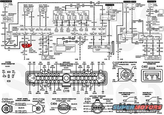
4WABS Circuit & Connectors
IF THE IMAGE IS TOO SMALL, click it.
'93 Bronco shown; '94-96 Bronco similar.
Front Wheel Speed Sensor Motorcraft BRAB30; Airtex ; Dorman 970-020; Standard ALS185; Motoneo F4TZ2C204A; Raybestos ABS530392; APDTY 081131
Rear axle ABS sensor (DY1123, F85Z-9E731-AB)
To bypass a suspected bad module, unplug the connector & install jumper wires: pin 1 (or 14; circuit 530 LG/Y) to 21 (519 LG/BK); pin 22 (523 R/Pk) to 39 (491 Or/LB). This shuts down ABS completely, but sends the ABS sensor signal directly to the PSOM for proper transmission (etc.) control.
 .
.  .
. 
Compare to:

For relay locations, see:

This document is a detailed wiring diagram for the Ford 4WABS (four-wheel anti-lock brake system). It maps the complete circuit from power sources (fuse panel fuse 17 10A and fuse 13 15A, plus engine compartment fuse box 30A and 15A feeds) through the 4WABS control module, hydraulic control unit, pump motor, relays, and wheel-speed sensors. Each circuit number and wire color is labeled (e.g., 532 O/Y vehicle power, 530 LG/Y grounds, 516 Y/BK right front sensor low, 522 T/BK left front sensor low), along with component resistance specs: wheel and rear axle sensors 800-1400 ohms, iso valves 5-8 ohms, dump valves 3-6 ohms, pump motor speed sensor 5-40 ohms at ≥150 Hz. The lower half provides connector pinout drawings: the gray 40-pin C119 control-module connector, C122 pump motor connector, C402 acceleration sensor connector, C123/C124 front wheel sensor connectors, C404 rear axle sensor connector, C121 hydraulic control unit connector, and pump motor relay #2 and main relay #1 connectors, most identified by harness part number 12A581. Grounds (G100, G101), splices, the anti-lock warning indicator in the instrument cluster, the brake on/off switch feed to the PCM, and the programmable speedometer/odometer module speed-signal circuit (491 O/LB) are all shown, making this a complete diagnostic reference for tracing 4WABS electrical faults.
Is this accurate? Sign in to help verify it.
Frequently asked questions
- What resistance should the 4WABS wheel speed sensors read?
- The right front, left front, and rear axle sensors are all specified at 800-1400 ohms on the diagram.
- What are the resistance specs for the hydraulic control unit valves?
- The iso valves are 5-8 ohms and the dump valves are 3-6 ohms per the diagram.
- What wire color is the 4WABS vehicle power circuit?
- Circuit 532, orange/yellow (O/Y), feeds vehicle power to pin 17 of the 4WABS control module, protected by 30A fuses in the engine compartment fuse box.
- Which connector is the 4WABS control module connector and what color is it?
- C119, a gray connector (part 12A581) with pins numbered up to 40, shown with full pinout including circuits like 530 LG/Y grounds at pins 1 and 14.
- What is the pump motor speed sensor specification?
- The pump motor speed sensor is listed as 5-40 ohms at ≥150 Hz, connected via circuits 462 (P) and 604 (O/R) at connector C122.
Comments
More from this build







No comments yet.