Nissan Micra Carburetor Exploded Diagram - Throttle Chamber & Center Body Parts
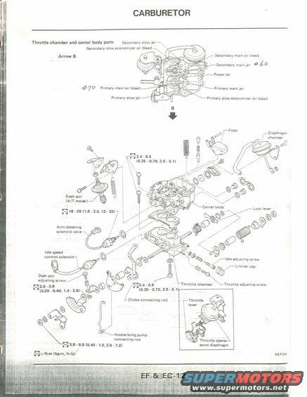
Exploded parts diagram of carburetor throttle chamber and center body components.
This document is a scanned page from a factory service manual (page EF & EC-12, figure reference SEF04) covering the carburetor, specifically the throttle chamber and center body parts. The top portion shows a view of the carburetor as seen from "Arrow B," labeling the jets and air bleeds: secondary slow jet, secondary slow economizer air bleed, secondary main air bleed, secondary main jet (with a handwritten annotation "#60"), power jet, primary main air bleed (handwritten "#70"), primary main jet, primary slow jet, and primary slow economizer air bleed. The lower portion is an exploded parts diagram of the carburetor center body and throttle chamber, identifying components such as the float, diaphragm chamber, dash pot (A/T model), center body, lock lever, anti-dieseling solenoid valve, idle speed control solenoid, idle adjusting screw, limiter cap, dash pot adjusting screw, throttle chamber, throttle adjusting screw, choke connecting rod, throttle lever, accelerating pump connecting rod, and throttle opener servo diaphragm. Torque specifications are given in N·m (kg-m, ft-lb) for several fasteners, ranging from 2.0-3.9 N·m for small screws up to 18-29 N·m for the anti-dieseling solenoid valve. This page is useful for anyone disassembling or reassembling the carburetor and needing correct part identification and fastener torque values.
Is this accurate? Sign in to help verify it.
Frequently asked questions
- What is the torque spec for the anti-dieseling solenoid valve?
- The diagram shows 18 - 29 N·m (1.8 - 3.0 kg-m, 13 - 22 ft-lb) for the anti-dieseling solenoid valve area.
- What torque should the throttle chamber and center body screws get?
- Both are marked 3.4 - 6.9 N·m (0.35 - 0.70 kg-m, 2.5 - 5.1 ft-lb).
- What jets and air bleeds are shown on the carburetor?
- Secondary slow jet, secondary slow economizer air bleed, secondary main air bleed, secondary main jet, power jet, primary main air bleed, primary main jet, primary slow jet, and primary slow economizer air bleed. Handwritten annotations note #60 for the secondary main jet and #70 near the primary main air bleed.
- What are the main components in the exploded carburetor diagram?
- Float, diaphragm chamber, dash pot (A/T model), center body, lock lever, anti-dieseling solenoid valve, idle speed control solenoid, idle adjusting screw, limiter cap, dash pot adjusting screw, throttle chamber, throttle adjusting screw, choke connecting rod, throttle lever, accelerating pump connecting rod, and throttle opener servo diaphragm.
- What units are the torque values given in?
- The legend states the torque symbol values are in N·m (kg-m, ft-lb).
Comments
More from this build











No comments yet.