1984 Ford Bronco II Exhaust Plan Diagram - Flowmaster 40 Delta, 2.5" Turn Downs

Reference · 1984-1990 Bronco IIAll 7 schematics
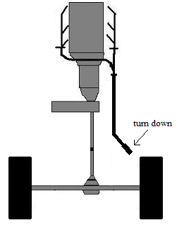
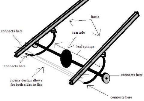
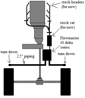
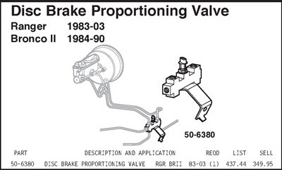
Schematic exhaust routing diagram depicting stock headers, catalytic converter, Flowmaster 40 muffler, 2.5 inch piping and turn-downs.
Part of 1984-1990 Ford Bronco II Schematics
This is a hand-drawn exhaust system plan (schematic) uploaded to a 1984 Ford Bronco II gallery, showing a planned dual turn-down exhaust layout viewed from above/behind the vehicle. The drawing depicts the engine with stock headers labeled "(for now)", feeding into the stock catalytic converter (also labeled "for now"), then into a Flowmaster 40 delta series muffler. From the muffler, 2.5-inch piping runs to both sides of the vehicle, ending in turn-downs on the left and right ahead of the rear axle. The rear axle and wheels are shown at the bottom of the sketch for spatial reference. A reader can learn the intended exhaust routing: single path from headers through the stock cat into a single Flowmaster 40 Series Delta muffler, splitting into dual 2.5" pipes exiting via turn-downs on each side before the rear axle. The document contains no year, model, engine, torque, or part-number data beyond the muffler description; the "for now" notations indicate the headers and catalytic converter are temporary and slated for future replacement. This appears to be one page of a two-image set (the companion image is "exhaust path.jpg").
Is this accurate? Sign in to help verify it.
Frequently asked questions
- What muffler is planned in this exhaust diagram?
- A Flowmaster 40 delta series muffler, placed after the stock catalytic converter.
- What size exhaust piping is specified?
- 2.5" piping running from the muffler to turn-downs on both sides.
- Are the headers and catalytic converter being replaced?
- The diagram labels both the stock headers and stock cat as "(for now)", indicating they are being retained temporarily.
- How does the exhaust exit in this plan?
- Dual turn-downs, one on each side of the vehicle, located ahead of the rear axle.

No comments yet.