SuperMotors SuperMotors SUPERMOTORS Search: try “orange Bronco on 35s”
Home/ Registry/ Ford/ Bronco/ 1992-1996/ “The Bronco”/ Photo supermotors.net/registry/media/254838

Ford Bronco Fuel Pump Inertia Switch Reset Button Diagram - Open vs Closed

Diagram of inertia fuel shutoff switch showing open position and reset button
Diagram of inertia fuel shutoff switch showing open position and reset buttonOriginal file
Diagram of inertia fuel shutoff switch showing open position and reset button

Reference · 1992-1996 BroncoAll 98 manual pages
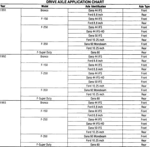
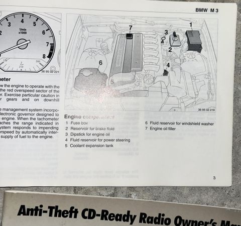
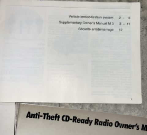
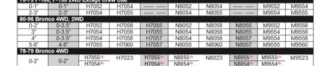
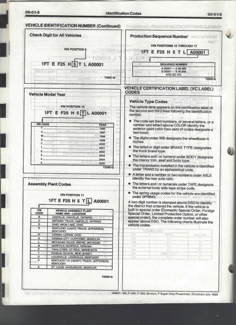
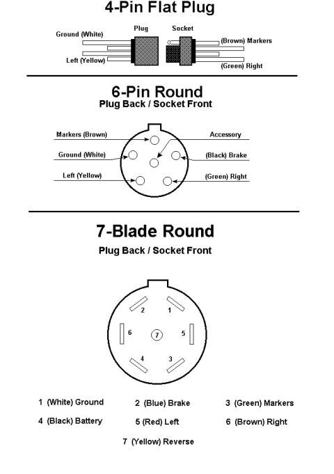
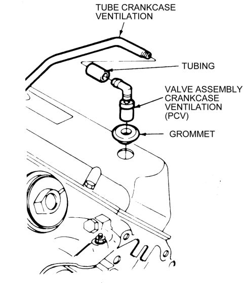
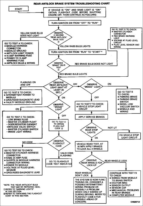
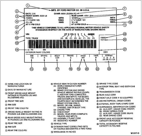
'91-93 Ford truck drive axle application chart for Bronco, F-150, F-250, F-350 and F-Super Duty Ford Throttle Position Sensor (TPS) Location Diagram - Throttle Body Assembly Ford TP (Throttle Position) Sensor Voltage vs. Angle Graph: 1992 Bronco 1987-1993 Ford transfer case application chart for Bronco and F-Series, Borg-Warner 13-56 and 13-45 1992 Ford Bronco & F-Series RABS Component Location Diagram - Rear Antilock Rear ABS (RABS) flash-out code chart listing yellow REAR ABS light flashes 1 through 16 or more Ford Bronco Fuel Pump Inertia Switch Reset Button Diagram - Open vs Closed 1992 Ford Bronco PCV Valve Vacuum Test Illustration - Finger Suction Check BMW M3 Owner's Manual Page 3 - Engine Compartment Component Locations Supplementary Owner's Manual M3 Contents - Vehicle Immobilization System Index Lift kit part number table for 80-96 Bronco 4WD, 2WD and 78-79 Bronco 4WD by lift height 1996 F-Series and Bronco manual page 00-01-8 on VIN check digit, model year and plant codes 98manual pages1992-1996 Ford Bronco More reference Trailer Connector Wiring Diagram - 4-Pin Flat, 6-Pin Round & 7-Blade PinoutsWiring diagram Ford Bronco PCV Valve & Crankcase Ventilation Tube Exploded DiagramExploded parts Ford RABS Rear Antilock Brake System Troubleshooting Chart (1992 Bronco)Service procedure Ford truck certification label with 25 numbered callouts explaining GVWR, tire, VIN and code fieldsSpec plate 1992 Ford Bronco/F-Series 5.0L 5.8L Engine Compartment Connector LocationsSchematic Ford 5.0L V8 Vacuum Hose Routing Diagram - EGR, AIR, FPRC & Carbon CanisterVacuum routing Ford 255/302/351W & 351M/400 V8 Intake Manifold Bolt Tightening SequenceTorque spec Brake Booster to Master Cylinder Adapter Plate Blueprint - Ford Bronco SwapBlueprint 1994-1995 BMW 3 Series Owner's Manual Booklet Set - Warranty, Radio & AccessoriesBrochure Ford Bronco/F-Series Fuse 18 (10A) - Speedometer, Air Bag, Shift ControlFuse chart

Service manual figure of an inertia switch labeling the open-switch position and the reset button when closed.

Part of 1992-1996 Ford Bronco Manual Pages

AI caption · Photo 124 of 272

This document is a single line-art illustration from a Ford service manual showing the fuel pump inertia switch (fuel cutoff switch). The diagram depicts the switch assembly with its electrical connector terminals at the lower left and the reset button on top. Two callouts explain the reset button's positions: a dashed outline at the top labeled "POSITION FOR OPEN SWITCH" shows where the button sits when the switch has been tripped (fuel pump circuit open), and the solid outline labeled "RESET BUTTON (SWITCH CLOSED)" shows the depressed position when the switch is reset and the circuit is closed. The figure reference number A20827-A appears at the bottom right. A reader can learn how to visually identify whether the inertia switch has tripped (button popped up in the open position) and that pressing the reset button down restores the closed (normal operating) state. The illustration was uploaded to a 1992 Ford Bronco gallery and is consistent with the inertia/fuel shutoff switch used on Ford trucks of that era, though the drawing itself contains no year, model, or part number text.

Is this accurate? Sign in to help verify it.

Frequently asked questions

How can I tell if the Ford inertia switch has tripped?
The diagram shows the reset button in a raised, dashed-outline position labeled "POSITION FOR OPEN SWITCH", if the button is up in this position, the switch is open (tripped).
How do I reset the fuel pump inertia switch?
Press the reset button down; the diagram labels the depressed button position as "RESET BUTTON (SWITCH CLOSED)," indicating the switch is closed and reset when the button is pushed in.
Where is the reset button on the inertia switch?
Per the illustration, the reset button is on the top of the inertia switch assembly.

Comments

No comments yet.

More 1992-1996 Broncos