SuperMotors SuperMotors SUPERMOTORS Search: try “orange Bronco on 35s”
Home/ Registry/ Ford/ Bronco/ 1992-1996/ “The Bronco”/ Photo supermotors.net/registry/media/254905

Ford Throttle Position Sensor (TPS) Location Diagram - Throttle Body Assembly

Line drawing of throttle body assembly with throttle position sensor and screw
Line drawing of throttle body assembly with throttle position sensor and screwOriginal file
Line drawing of throttle body assembly with throttle position sensor and screw

Reference · 1992-1996 BroncoAll 101 manual pages
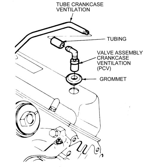
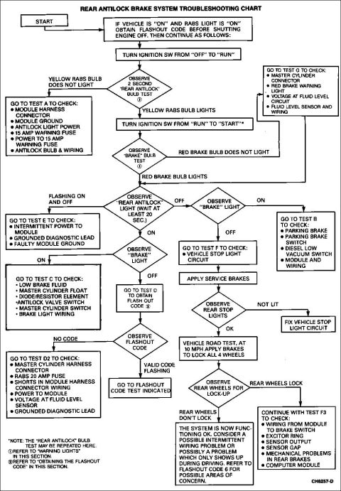
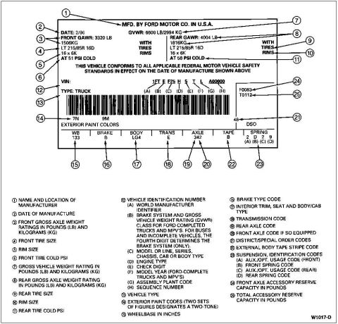
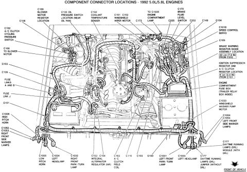
'91-93 Ford truck drive axle application chart for Bronco, F-150, F-250, F-350 and F-Super Duty Ford Throttle Position Sensor (TPS) Location Diagram - Throttle Body Assembly Ford TP (Throttle Position) Sensor Voltage vs. Angle Graph: 1992 Bronco 1987-1993 Ford transfer case application chart for Bronco and F-Series, Borg-Warner 13-56 and 13-45 1992 Ford Bronco & F-Series RABS Component Location Diagram - Rear Antilock Rear ABS (RABS) flash-out code chart listing yellow REAR ABS light flashes 1 through 16 or more Ford Bronco Fuel Pump Inertia Switch Reset Button Diagram - Open vs Closed 1992 Ford Bronco PCV Valve Vacuum Test Illustration - Finger Suction Check 1996 Ford Bronco Owner's Manual - Checking & Adding Engine Coolant 1996 Ford F-250/F-350 Diesel Nameplate & Power Stroke Emblem Removal - 01-08-7 1965 NHRA Rule Book Page 15 - Gas & Supercharged Gas Coupes/Sedans Classes Ford Bronco/F-Series Transfer Case Removal, Torque Specs & NP208 Exploded View 101manual pages1992-1996 Ford Bronco More reference Trailer Connector Wiring Diagram - 4-Pin Flat, 6-Pin Round & 7-Blade PinoutsWiring diagram Ford Bronco PCV Valve & Crankcase Ventilation Tube Exploded DiagramExploded parts Ford RABS Rear Antilock Brake System Troubleshooting Chart (1992 Bronco)Service procedure Ford truck certification label with 25 numbered callouts explaining GVWR, tire, VIN and code fieldsSpec plate 1992 Ford Bronco/F-Series 5.0L 5.8L Engine Compartment Connector LocationsSchematic Ford 5.0L V8 Vacuum Hose Routing Diagram - EGR, AIR, FPRC & Carbon CanisterVacuum routing Ford 255/302/351W & 351M/400 V8 Intake Manifold Bolt Tightening SequenceTorque spec Smittybilt XRC Gen 3 Winch Box - 9.5K/12K Recovery Winch Features & CalloutsBrochure Brake Booster to Master Cylinder Adapter Plate Blueprint - Ford Bronco SwapBlueprint Ford Bronco/F-Series Fuse 18 (10A) - Speedometer, Air Bag, Shift ControlFuse chart

Service manual illustration of a throttle body assembly with the throttle position sensor and mounting screw called out.

Part of 1992-1996 Ford Bronco Manual Pages

AI caption · Photo 153 of 272

This document is a line-art exploded-view illustration showing the throttle position sensor (TPS) mounting location on a Ford throttle body assembly. The drawing depicts a two-barrel (dual bore) throttle body with the throttle position sensor removed and positioned in front of its mounting boss, with a single mounting screw shown separately below. Three callout labels with arrows identify the components: "THROTTLE BODY ASSEMBLY" pointing to the main throttle body casting, "THROTTLE POSITION SENSOR" pointing to the removed sensor, and "SCREW" pointing to the retaining screw. Dashed alignment lines indicate how the sensor and screw install onto the side of the throttle body at the throttle shaft. A reader can learn where the TPS is located on the throttle body, its orientation during installation/removal, and that it is retained by a screw. The illustration contains no part numbers, torque specifications, year/model statements, or written procedures, it serves purely as a component identification and location diagram, likely accompanying a service manual procedure for TPS removal, installation, or testing. It was uploaded to a 1992 Ford Bronco gallery, though the diagram itself does not state a vehicle application.

Is this accurate? Sign in to help verify it.

Frequently asked questions

Where is the throttle position sensor located?
According to the diagram, the throttle position sensor mounts on the side of the throttle body assembly, aligned with the throttle shaft.
How is the throttle position sensor attached to the throttle body?
The diagram shows the sensor is retained by a screw, illustrated separately with dashed alignment lines showing installation.
What components are labeled in this diagram?
Three items are labeled: the throttle body assembly, the throttle position sensor, and the screw that retains the sensor.


Comments

No comments yet.

More 1992-1996 Broncos