Ford TP (Throttle Position) Sensor Voltage vs. Angle Graph: 1992 Bronco

Reference · 1992-1996 BroncoAll 101 manual pages
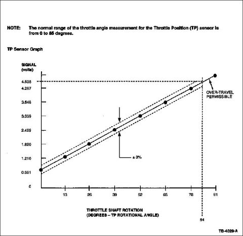
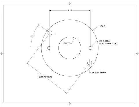

Service manual graph of throttle position (TP) sensor output voltage versus throttle shaft rotation with normal range.
Part of 1992-1996 Ford Bronco Manual Pages
This document is a Throttle Position (TP) sensor reference graph, likely a page from a Ford service manual (figure reference TB-4028-A). It plots TP sensor signal voltage against throttle shaft rotation in degrees (TP rotational angle). A note states that the normal range of throttle angle measurement for the TP sensor is 0 to 85 degrees. The graph shows a linear relationship between throttle rotation and output voltage, with plotted data points at approximately 13, 26, 39, 52, 65, 78, and 81 degrees, corresponding to voltages ranging from roughly 0.601 V near closed throttle up to about 4.538 V near 84 degrees of rotation. A ±3% tolerance band is drawn as dashed lines on either side of the nominal line, indicating acceptable sensor variation. Beyond about 84 degrees / 4.538 volts, the graph marks a region labeled "OVER-TRAVEL PERMISSIBLE," indicating the sensor may travel past the normal measurement range without fault. A technician can use this chart to verify that measured TP sensor voltage at a given throttle angle falls within the specified ±3% tolerance, helping diagnose a faulty or misadjusted TP sensor.
Is this accurate? Sign in to help verify it.
Frequently asked questions
- What is the normal throttle angle measurement range for the TP sensor?
- The document states the normal range of the throttle angle measurement for the Throttle Position (TP) sensor is from 0 to 85 degrees.
- What voltage should the TP sensor read near full throttle?
- According to the graph, the signal reaches approximately 4.257 volts around 78 degrees and about 4.538 volts near 84 degrees of throttle shaft rotation.
- What tolerance is allowed on the TP sensor signal?
- The graph shows a ±3% tolerance band (dashed lines) around the nominal voltage-versus-angle line.
- Is over-travel of the TP sensor acceptable?
- Yes: the graph labels the region beyond about 84 degrees / 4.538 volts as 'OVER-TRAVEL PERMISSIBLE.'
- What is the approximate TP sensor voltage at low throttle angles?
- The graph shows about 0.601 volts near closed throttle and roughly 1.210 volts at about 13 degrees of rotation.



No comments yet.