Nissan R22T Manual Steering Gear Assembly & Pinion Torque Adjustment (ST-9)
Steering shop manual page ST-9: adjusting-screw torque 4.9 N·m then backed off 40-50°, with pinion rotating-torque average 1.0-1.4 N·m (max 1.5, min 0.3 N·m).
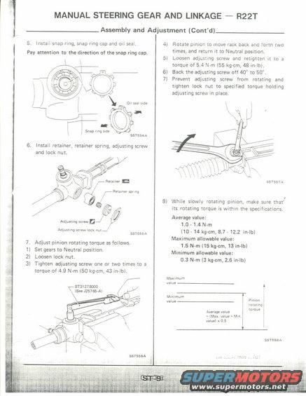
This is a page from a Nissan service manual covering assembly and adjustment of the R22T manual steering gear (rack and pinion) and linkage, page ST-9. It continues the assembly procedure: step 5 covers installing the snap ring, snap ring cap and oil seal, with a diagram showing correct orientation (oil seal side vs. snap ring side, illustration SST554A). Step 6 covers installing the retainer, retainer spring, adjusting screw and lock nut (SST555A). Step 7 details the pinion rotating torque adjustment: set gears to Neutral, loosen the lock nut, tighten the adjusting screw to 4.9 N·m (50 kg-cm, 43 in-lb) using tool ST3127S000 (see J25765-A), rotate the pinion to move the rack back and forth twice, retighten the adjusting screw to 5.4 N·m (55 kg-cm, 48 in-lb), back it off 40° to 50°, then tighten the lock nut while holding the adjusting screw. Step 8 gives pinion rotating torque specifications: average value 1.0-1.4 N·m (10-14 kg-cm, 8.7-12.2 in-lb), maximum allowable 1.5 N·m (15 kg-cm, 13 in-lb), minimum allowable 0.3 N·m (3 kg-cm, 2.6 in-lb), with a chart illustrating that average value equals (max + min) x 0.5.
Is this accurate? Sign in to help verify it.
Frequently asked questions
- What is the pinion rotating torque specification for the R22T manual steering gear?
- Average value: 1.0 - 1.4 N·m (10 - 14 kg-cm, 8.7 - 12.2 in-lb); maximum allowable: 1.5 N·m (15 kg-cm, 13 in-lb); minimum allowable: 0.3 N·m (3 kg-cm, 2.6 in-lb).
- How do you adjust the pinion rotating torque on the R22T steering rack?
- Set gears to Neutral, loosen the lock nut, tighten the adjusting screw one or two times to 4.9 N·m (50 kg-cm, 43 in-lb), rotate the pinion to move the rack back and forth twice and return to Neutral, loosen and retighten the adjusting screw to 5.4 N·m (55 kg-cm, 48 in-lb), back the screw off 40° to 50°, then tighten the lock nut to specified torque while holding the adjusting screw.
- What special tool is used for the R22T adjusting screw torque?
- Tool ST3127S000 (See J25765-A) is shown for tightening the adjusting screw.
- How is the average pinion rotating torque value calculated?
- The chart shows: Average value = (Max. value + Min. value) x 0.5.
- What should you watch for when installing the snap ring cap?
- Pay attention to the direction of the snap ring cap — the diagram distinguishes the oil seal side from the snap ring side.
Comments
More from this build


No comments yet.