Home/
Registry/
Ford/
Excursion/
2000-2005/
“Diesel Wagon”/
Photo
supermotors.net/registry/media/454260
Ford Electrochromatic Mirror Connector C911 Pinout - Wire Colors & Circuits
Reference · 2000-2005 ExcursionAll 7 wiring diagrams
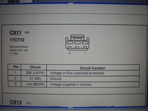
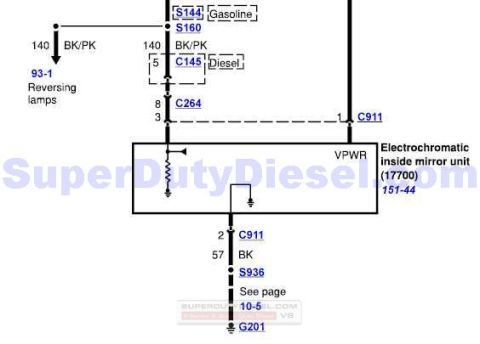
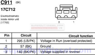

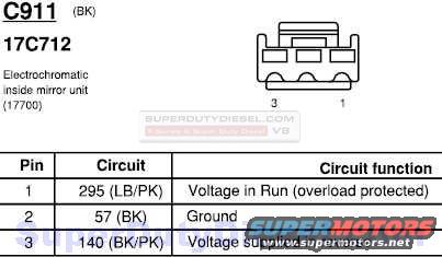
Connector pinout diagram for C911 electrochromatic mirror showing three pins with circuit color codes and functions.
Part of 2000-2005 Ford Excursion Wiring Diagrams
This document is a connector pinout reference page for connector C911 (a black, 3-pin connector, base part number 17C712) that mates to the electrochromatic (auto-dimming) inside rear-view mirror unit (base part number 17700). It includes a face-view drawing of the 3-cavity connector with cavity positions 1 and 3 labeled, plus a pinout table. Pin 1 carries circuit 295, a light blue/pink (LB/PK) wire providing voltage in Run (overload protected). Pin 2 carries circuit 57, a black (BK) wire serving as ground. Pin 3 carries circuit 140, a black/pink (BK/PK) wire that provides voltage when the vehicle is in reverse (used so the mirror stops dimming during backing). A reader can use this page to identify wire colors and circuit numbers when diagnosing or wiring an electrochromatic mirror, such as troubleshooting power, ground, or the reverse-signal input at the mirror connector. The scan was uploaded to a 2002 Ford Excursion gallery; the page itself does not state a year or model, but its format and circuit numbering are consistent with Ford wiring documentation.
Is this accurate? Sign in to help verify it.
Frequently asked questions
- What are the pin functions of connector C911 for the electrochromatic inside mirror?
- Pin 1: circuit 295 (LB/PK), voltage in Run (overload protected); Pin 2: circuit 57 (BK), ground; Pin 3: circuit 140 (BK/PK), voltage supplied in reverse.
- What wire color is the ground for the auto-dimming mirror connector C911?
- The ground is pin 2, circuit 57, a black (BK) wire.
- Which wire on the electrochromatic mirror gets power when the vehicle is in reverse?
- Pin 3, circuit 140, a black/pink (BK/PK) wire, receives voltage when the vehicle is in reverse.
- What part numbers appear on this mirror connector diagram?
- The connector C911 is identified with base part number 17C712, and the electrochromatic inside mirror unit is part number 17700.
- How many pins does the electrochromatic mirror connector C911 have?
- It is a 3-pin (3-cavity) black connector, with cavities 1 through 3 shown in the face-view drawing.




No comments yet.