Home/
Registry/
Ford/
Excursion/
2000-2005/
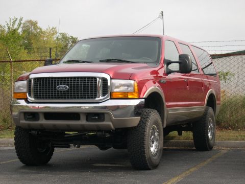
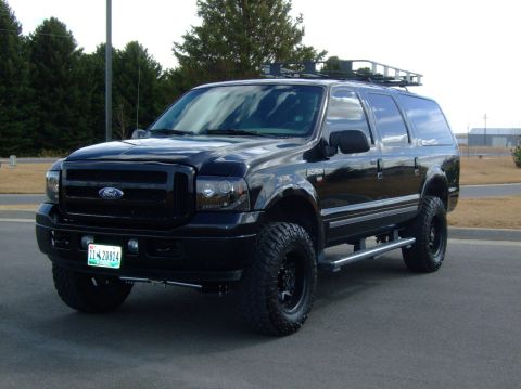
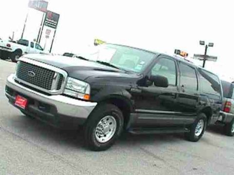
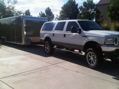
“Diesel Wagon”/
Photo
supermotors.net/registry/media/500549
Ford C911 Connector Pinout - Auto-Dimming Interior Mirror Wiring (17700)

Reference · 2000-2005 ExcursionAll 7 wiring diagrams
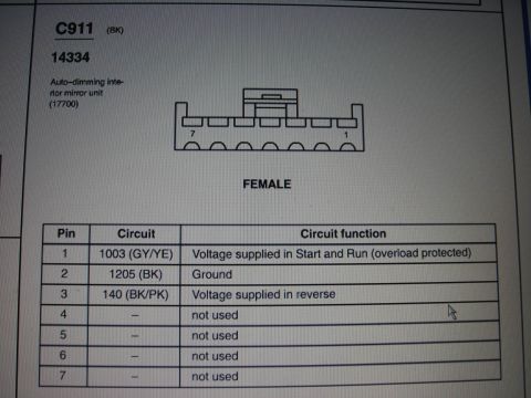
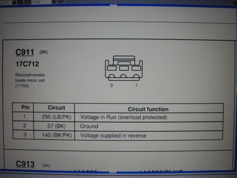
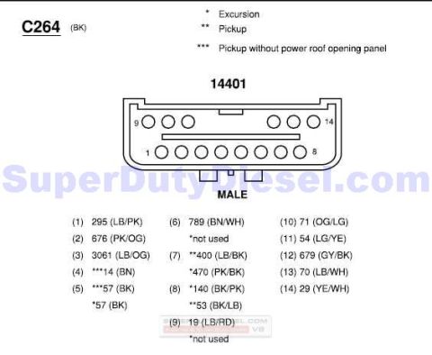
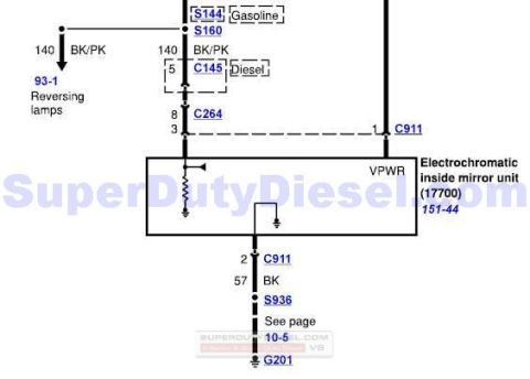
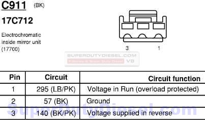

Connector pinout diagram for the C911 female auto-dimming mirror connector with a seven-pin circuit and function table.
Part of 2000-2005 Ford Excursion Wiring Diagrams
This document is a connector pinout page from a Ford wiring/connector reference showing connector C911 (BK, black), part of harness 14334, which mates to the auto-dimming interior mirror unit (base part number 17700). A drawing depicts the 7-cavity female connector with pin positions numbered 7 through 1. A table lists each pin's circuit number, wire color, and function: Pin 1 uses circuit 1003 (gray/yellow wire) and supplies voltage in Start and Run (overload protected); Pin 2 uses circuit 1205 (black wire) for ground; Pin 3 uses circuit 140 (black/pink wire) and supplies voltage in reverse; Pins 4 through 7 are not used. This page is useful for anyone diagnosing, repairing, or retrofitting an auto-dimming rearview mirror, for example, testing for switched power at pin 1, ground at pin 2, and the reverse signal at pin 3 that disables mirror dimming when backing up. The page was uploaded to a 2002 Ford Excursion gallery alongside other rear-mirror wiring pages, though the document itself does not state a year or model.
Is this accurate? Sign in to help verify it.
Frequently asked questions
- What is connector C911?
- C911 (BK) is the 7-pin female connector on harness 14334 that connects to the auto-dimming interior mirror unit (17700).
- Which pin on C911 supplies power to the auto-dimming mirror?
- Pin 1, circuit 1003 (GY/YE wire), supplies voltage in Start and Run and is overload protected.
- Which pin is ground on the auto-dimming mirror connector?
- Pin 2, circuit 1205 (BK wire), is the ground.
- What does pin 3 of C911 do?
- Pin 3, circuit 140 (BK/PK wire), supplies voltage in reverse.
- Are all seven pins of C911 used?
- No. Only pins 1-3 are used; pins 4, 5, 6, and 7 are listed as not used.
No comments yet.