Home/
Registry/
Ford/
Excursion/
2000-2005/
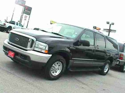
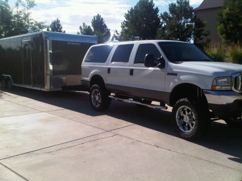
“Diesel Wagon”/
Photo
supermotors.net/registry/media/454261
Ford Excursion/Super Duty Auto-Dim Inside Mirror Wiring Diagram (17700)
Reference · 2000-2005 ExcursionAll 7 wiring diagrams
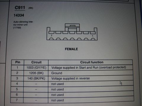
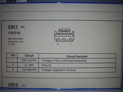
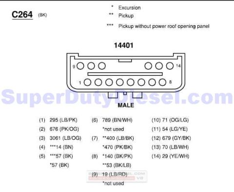
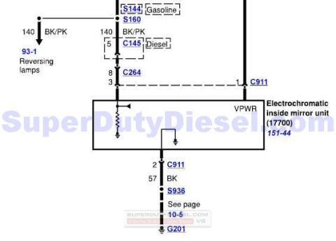
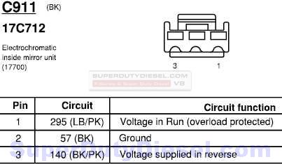

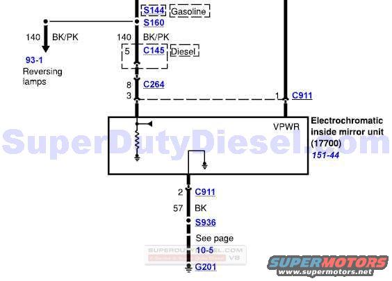
Wiring diagram for the electrochromatic inside mirror showing color-coded wires, splices, and connector references to ground.
Part of 2000-2005 Ford Excursion Wiring Diagrams
This document is one page of a Ford wiring diagram showing the power and ground circuits for the electrochromatic (auto-dimming) inside rear-view mirror unit, base part number 17700, cross-referenced to diagram cell 151-44. Power arrives on circuit 140 (wire color BK/PK, black/pink) from splices S144 (gasoline engine applications) and S160, with a branch feeding the reversing lamps circuit (referenced to page/cell 93-1). For diesel applications the circuit passes through connector C145 pin 5, then connector C264 pin 8, entering the mirror at pin 3. A VPWR (vehicle power) feed enters the mirror unit at connector C911 pin 1. The ground path leaves the mirror at C911 pin 2 on circuit 57 (BK, black wire), passes through splice S936, and terminates at ground G201, with a note to see page 10-5. The diagram distinguishes gasoline versus diesel wiring paths, making it useful for diagnosing an inoperative auto-dimming mirror or reverse-tilt mirror wiring on Ford Super Duty / Excursion-family trucks. The page carries a SuperDutyDiesel.com watermark. No explicit model year is printed on this excerpt.
Is this accurate? Sign in to help verify it.
Frequently asked questions
- What wire color and circuit feed the electrochromatic inside mirror?
- Circuit 140, a BK/PK (black/pink) wire, feeds the mirror; on diesel applications it passes through connector C145 pin 5 and C264 pin 8 into pin 3, and VPWR enters at C911 pin 1.
- How is the auto-dimming mirror grounded?
- Ground exits the mirror at connector C911 pin 2 on circuit 57 (BK wire), goes through splice S936, and terminates at ground G201 (see page 10-5).
- What is the part reference for the electrochromatic inside mirror unit?
- The diagram labels it as the Electrochromatic inside mirror unit (17700), diagram reference 151-44.
- Does the diagram differ between gasoline and diesel engines?
- Yes. Splice S144 is marked 'Gasoline,' while connector C145 (pin 5) is marked 'Diesel' on the 140 BK/PK circuit.
- What other circuit shares the 140 BK/PK wire?
- A branch of circuit 140 BK/PK goes to the reversing lamps, referenced at 93-1.
No comments yet.