Diagram of 1992-96 A/C heater control positions and airflow modes

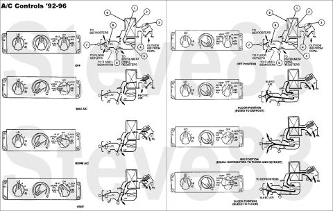
Air Conditioning Controls for '92-96 A/C
IF THE IMAGE IS TOO SMALL, click it.
'80-86 & late-'88-91 work similarly.
OFF
In the OFF position, all doors are in the vacuum-applied position with the exception of the PANEL door. The blower & compressor clutch circuits are not energized.
MAX A/C
In the MAX A/C position, all vacuum operated doors are in the vacuum position. A/C damper inlet door (19C802) air is shut off and the passenger compartment air is recirculated to maximize cooling. Discharge is through panel register. A/C clutch & blower circuits are energized.
NORM A/C
In the NORM A/C position, outside air is allowed to enter the passenger compartment. The air passes through the A/C evaporator core (19860) and is cooled before reaching the passenger compartment. Discharge is through panel register. A/C clutch & blower circuits are energized.
VENT
Ventilation is delivered through the instrument panel registers when the function selector knob in the A/C control (19980) is set in the VENT position. In the VENT position, no vacuum is applied to the OUTSIDE/RECIRC. vacuum control motor (18A318 ) and the door is open to the outside. The air coming in through the cowl is discharged through the panel registers. The blower circuit is energized, but the A/C clutch is not.
FLOOR
In the FLOOR position, no vacuum is applied to the vacuum control motor and the OUTSIDE/RECIRC. door is open to the outside. Air is discharged through the heater outlet floor ducts (18C433) with a small amount going to the windshield defroster hose nozzles (18490). The blower circuit is energized, but the A/C clutch is not.
MIX
In the MIX position, outside air is discharged through the windshield defroster hose nozzles and the heater outlet floor ducts. A/C clutch & blower circuits are energized.
DEFROST
In the DEFROST position, outside air is discharged through the windshield defroster hose nozzles with a small amount going to the heater outlet floor ducts. All doors are in the no vacuum position. A/C clutch is engaged in ambient temperatures above approximately 10%uFFFDC (50%uFFFDF) & the blower circuit is energized.
The PANEL/FLOOR, FLOOR/DEFROST and OUTSIDE/RECIRC doors are vacuum operated.
For maximum cooling, the temperature knob should be set in its fully counterclockwise position; the function knob should be in the MAX A/C position; and the blower motor (18527) should be set for a desired rate of airflow.
Even though the function knob is on MAX A/C, the temperature knob, being manually controlled, may be set to modify the temperature of the air and the path through which the air flows. Another characteristic of the MAX A/C setting is the increased noise level of the blower motor. Speed does not change when the OUTSIDE/RECIRC. door is moved to either of its two positions. The difference in noise level is that an open recirculation door exposes the passenger compartment directly to the noise. When insulated against the noise with the recirculation passageway closed, the speed appears to be less.
The control knob operates an A/C switch that is attached to the backside of the A/C control by one screw and retainer tabs.
Five hoses (black, white, red, blue, yellow) extend from the A/C control just below the electrical connector for the mode selector switch to the vacuum control motors and vacuum supply. The solid black hose goes to the vacuum supply through a tee-shaped A/C vacuum check valve (19A563), which attaches the A/C vacuum reservoir tank and bracket (19A566) and engine source. The white hose actuates the OUTSIDE/RECIRC. air door two-position vacuum control motor. The blue hose actuates the FLOOR/PANEL air door two-position vacuum control motor. The red and yellow hoses actuate the FLOOR/DEFROST three-position air vacuum control motor. Each end of each hose slides onto the nipple of the vacuum port to which it attaches. .
.  .
.  .
.  .
.  .
. 
This is the most common failure of this vacuum system:
Is this accurate? Sign in to help verify it.






No comments yet.