Home/
Registry/
Ford/
Crown Victoria/
1998-2011/
1999 Ford Crown Victoria/
Photo
supermotors.net/registry/media/516762
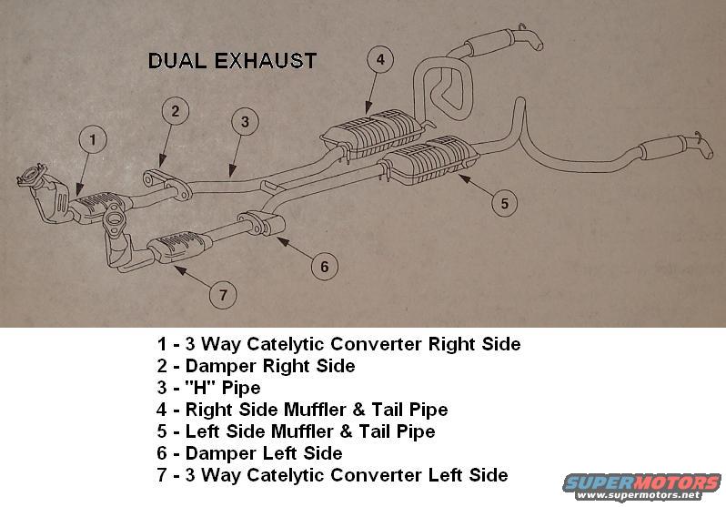
1999 Ford Crown Victoria Dual Exhaust System Diagram - Parts Layout
Reference · 1998-2011 Crown VictoriaAll 7 exploded parts diagrams



Dual exhaust system parts breakdown with numbered legend for catalytic converters, H-pipe, dampers, and mufflers.
Part of 1998-2011 Ford Crown Victoria Exploded Parts Diagrams
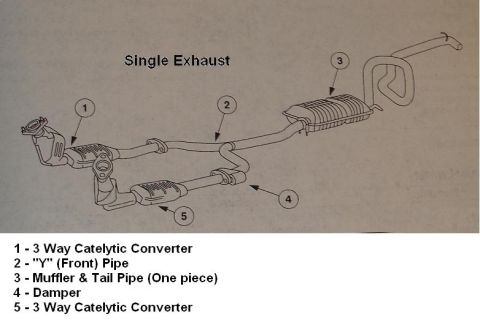
This document is a labeled exploded-view diagram of a dual exhaust system, uploaded to accompany a 1999 Ford Crown Victoria. The line drawing shows the complete exhaust layout from the engine-side connections rearward to the tailpipes, with seven numbered callouts identifying each major component. The legend identifies: (1) the 3-way catalytic converter on the right side, (2) a damper on the right side, (3) the "H" pipe that joins the two exhaust banks, (4) the right side muffler and tail pipe, (5) the left side muffler and tail pipe, (6) a damper on the left side, and (7) the 3-way catalytic converter on the left side. A reader can learn the relative positions and routing of the dual exhaust components, both catalytic converters at the front, the H-pipe crossover in the middle, dampers on each side, and dual mufflers with separate tailpipes at the rear. The document contains no part numbers, torque specifications, year/model text, or dimensions; it serves purely as a component identification and layout reference. It appears to be one page of a set that also includes a single exhaust diagram.
Is this accurate? Sign in to help verify it.
Frequently asked questions
- What components make up the dual exhaust system shown in this diagram?
- Seven components are labeled: a 3-way catalytic converter on each side (right and left), a damper on each side, an "H" pipe, and a muffler with tail pipe on both the right and left sides.
- How many catalytic converters are in the dual exhaust setup?
- Two: a 3-way catalytic converter on the right side (item 1) and a 3-way catalytic converter on the left side (item 7).
- What connects the two sides of the dual exhaust system?
- An "H" pipe (item 3) joins the exhaust between the catalytic converters and the mufflers.
- Does each side of the dual exhaust have its own muffler?
- Yes. Item 4 is the right side muffler & tail pipe and item 5 is the left side muffler & tail pipe.
- What are the dampers shown in the diagram?
- Items 2 and 6 are exhaust dampers, one on the right side pipe and one on the left side pipe, located between the catalytic converters and the H-pipe area.

No comments yet.