Home/
Registry/
Ford/
Crown Victoria/
1998-2011/
1999 Ford Crown Victoria/
Photo
supermotors.net/registry/media/516763
Ford Crown Victoria Single Exhaust System Diagram - Converters, Y-Pipe, Muffler

Reference · 1998-2011 Crown VictoriaAll 7 exploded parts diagrams
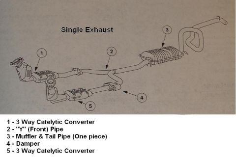



Single exhaust system parts breakdown with numbered legend for catalytic converters, Y-pipe, damper, and muffler.
Part of 1998-2011 Ford Crown Victoria Exploded Parts Diagrams
This document is an exploded-parts style line drawing of a single exhaust system, labeled "Single Exhaust." The illustration shows the complete exhaust layout from the exhaust manifold flanges rearward, with five numbered callouts identifying the major components. According to the legend: (1) a 3-way catalytic converter (spelled "Catelytic" in the document) on one bank, (2) the "Y" (front) pipe that merges the two banks into a single pipe, (3) a one-piece muffler and tail pipe assembly at the rear, (4) a damper mounted on the intermediate piping, and (5) a second 3-way catalytic converter on the other bank. The drawing shows the tailpipe routing upward and over the rear axle area before exiting. A reader can learn the component names, their relative positions, and the overall routing of a single-exhaust configuration for a V-engine vehicle (two converters merging into one Y-pipe). The document itself contains no year, make, model, part numbers, torque specs, or dimensions. It was uploaded to a 1999 Ford Crown Victoria gallery alongside a companion "Dual Exhaust" diagram, and nothing in the drawing contradicts that attribution.
Is this accurate? Sign in to help verify it.
Frequently asked questions
- What components make up the single exhaust system shown in this diagram?
- Two 3-way catalytic converters (items 1 and 5), a "Y" (front) pipe (item 2), a damper (item 4), and a one-piece muffler and tail pipe assembly (item 3).
- Are the muffler and tailpipe separate pieces in this exhaust system?
- No. Item 3 is labeled "Muffler & Tail Pipe (One piece)," indicating they are a single assembly.
- How many catalytic converters does this single exhaust system have?
- Two: items 1 and 5 are both labeled "3 Way Catelytic Converter," one on each bank, joining at the Y (front) pipe.
- What is item 4 in the single exhaust diagram?
- Item 4 is a damper mounted on the exhaust piping between the Y-pipe and the muffler.

No comments yet.