Home/
Registry/
Ford/
Crown Victoria/
1998-2011/
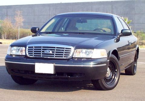
1999 Ford Crown Victoria/
Photo
supermotors.net/registry/media/525639
Ford Crown Victoria Charging System Wiring Diagram - Generator & Charge Indicator

Reference · 1998-2011 Crown VictoriaAll 29 wiring diagrams
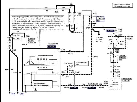
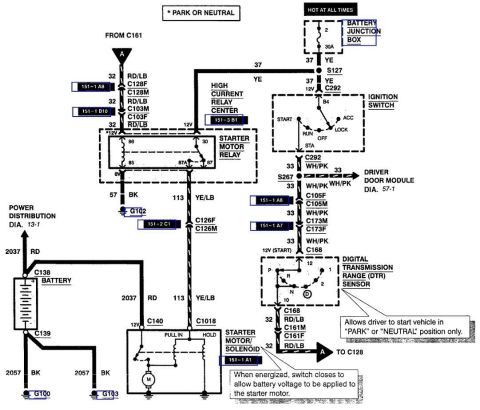
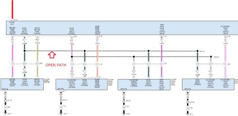
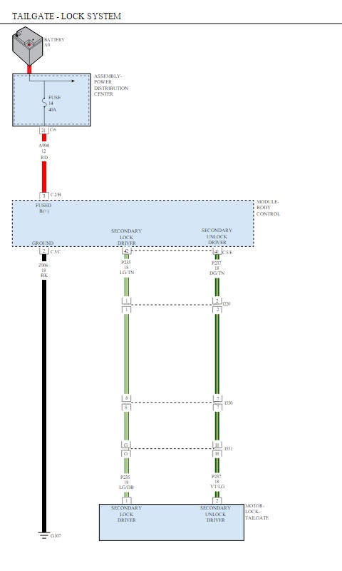
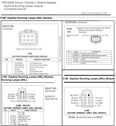
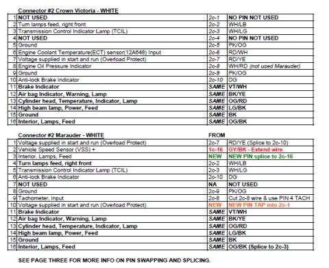
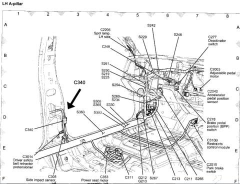
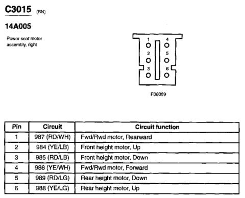
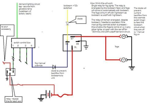


Wiring diagram of a Ford charging/generator system showing battery, starter solenoid, ignition switch and color-coded circuits with connector IDs.
Part of 1998-2011 Ford Crown Victoria Wiring Diagrams
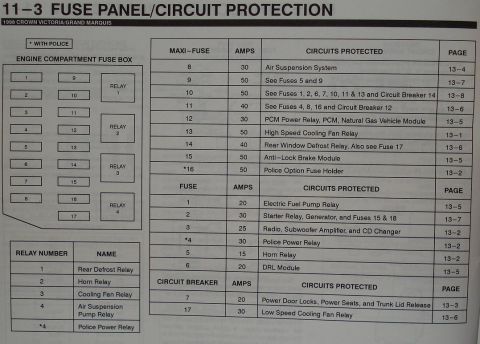
This document is a Ford charging system wiring diagram showing the generator (alternator) circuit. It traces power from the battery (connectors C138/C139) through circuit 2037 RD to splice S114, then through two 12-gauge gray fuse links (circuit 290 GY) and a 30A fuse (position 2) in the Battery Junction Box (C120), feeding circuit 37 YE to splice S127. From S127, power branches to the Starting System (diagram 20-1) and to the ignition switch (C292) via C123F/C123M. In RUN, circuit 489 PK/BK feeds a 10A fuse (position 15) in the Central Junction Box, then circuit 88 BK/WH through splice S231 to the instrument cluster charge indicator (connectors C251 with analog cluster, C256 with digital cluster; pins 8/7 and 9/10). Circuit 904 LG/RD runs from the cluster through C107F/C107M to the generator's I terminal. The generator's B+ output is circuit 38 BK/OG at C125; the A (sense) terminal is at C154 with circuit 36 YE/WH via splice S106. A note explains regulator operation: voltage on the I circuit activates the regulator, current flows from the A sense circuit to the field coil, AC output is rectified to DC at B+, and the S (stator) circuit feeds back roughly half battery voltage to turn off the charge indicator. Grounds G100 and G103 connect via circuit 2057 BK.
Is this accurate? Sign in to help verify it.
Frequently asked questions
- What fuse protects the charging circuit in the Battery Junction Box?
- Fuse position 2, a 30A fuse in the Battery Junction Box (C120), feeding circuit 37 YE.
- What size fuse feeds the charge indicator through the Central Junction Box?
- A 10A fuse in position 15 of the Central Junction Box, fed by circuit 489 PK/BK (12V in RUN) and outputting circuit 88 BK/WH.
- What wire color is the generator B+ output circuit?
- Circuit 38, BK/OG (black/orange), at connector C125 from the generator's B terminal.
- What fuse links protect the alternator output to the battery?
- Two 12-gauge gray fuse links on circuit 290 GY, connected at splice S114 to circuit 2037 RD from the battery.
- How does the voltage regulator turn off the charge indicator?
- Per the diagram note, the S (stator) circuit feeds back a voltage signal (typically half battery voltage) to the regulator, which is used to turn off the indicator.
- Which instrument cluster connectors are used for the charge indicator?
- C251 with the analog cluster and C256 with the digital cluster; pins 8 (analog)/7 (digital) receive circuit 88 BK/WH, and pins 9/10 output circuit 904 LG/RD to the generator I terminal.



No comments yet.