Home/
Registry/
Ford/
Crown Victoria/
1998-2011/
1999 Ford Crown Victoria/
Photo
supermotors.net/registry/media/523910
1999 Ford Crown Victoria Engine Bay Connector Locations - Relay Center Diagram

Reference · 1998-2011 Crown VictoriaAll 11 schematics
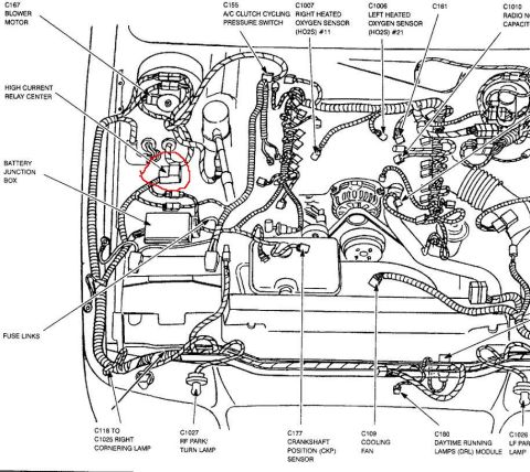
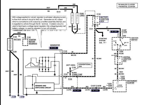
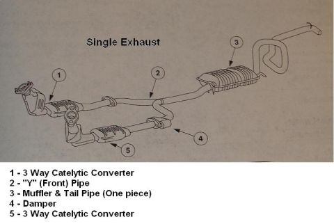
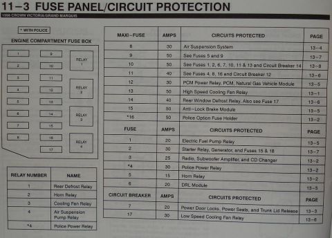

Underhood component/connector location view identifying right & left heated oxygen sensors (HO2S #11/#21), crankshaft position (CKP) sensor, A/C clutch cycling pressure switch, high-current relay center, battery junction box and fuse links.
Part of 1998-2011 Ford Crown Victoria Schematics
This document is an engine compartment component location diagram (schematic view labeled as an engine view) showing the front/engine bay of a vehicle, uploaded as applying to a 1999 Ford Crown Victoria. It is a line-art illustration with callout leaders identifying electrical connectors and components by connector number and name. Identified items include the C167 blower motor, the High Current Relay Center (circled in red on this scan), the Battery Junction Box, fuse links, C155 A/C clutch cycling pressure switch, C1007 right heated oxygen sensor (HO2S) #11, C1006 left heated oxygen sensor (HO2S) #21, C161, C1010 radio noise capacitor (partially cut off at the right edge), C118 to C1025 right cornering lamp, C1027 RF park/turn lamp, C177 crankshaft position (CKP) sensor, C109 cooling fan, C180 daytime running lamps (DRL) module, and C1026 LF park lamp (partially cut off). A reader can use this diagram to physically locate these connectors and components in the engine bay, particularly the High Current Relay Center and Battery Junction Box highlighted for fuse/relay troubleshooting. No fuse amperages, wire colors, or year/model text appear on the page.
Is this accurate? Sign in to help verify it.
Frequently asked questions
- Where is the High Current Relay Center located?
- Per the diagram, the High Current Relay Center is in the engine compartment near the blower motor and Battery Junction Box on the driver's side; it is circled in red on this scan.
- What connector number is the crankshaft position (CKP) sensor?
- The diagram labels the crankshaft position (CKP) sensor as connector C177, located low on the front of the engine.
- Which connectors are the heated oxygen sensors?
- C1007 is the right heated oxygen sensor (HO2S) #11 and C1006 is the left heated oxygen sensor (HO2S) #21.
- What connector goes to the cooling fan?
- The cooling fan connector is labeled C109 in the diagram.
- Where are the fuse links shown?
- The fuse links are called out near the Battery Junction Box area in the front driver's side of the engine compartment.


No comments yet.