Home/
Registry/
Ford/
F-150/
1975-1979/
1979 Ford F-150/
Photo
supermotors.net/registry/media/1129826
Ford 2G Alternator Wiring Diagram - Regulator Terminals, Wire Colors & Fuses
Reference · 1975-1979 F-150All 10 wiring diagrams
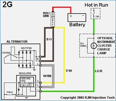



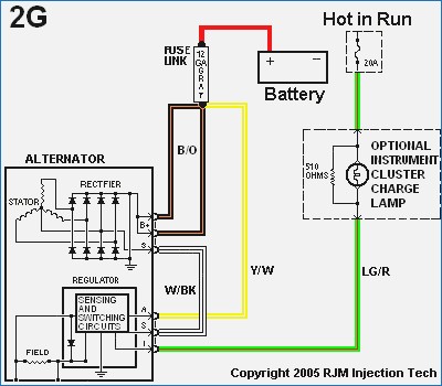
color-coded wiring diagram of a Ford 2G alternator charging circuit with fuse link, internal regulator and instrument-cluster charge lamp.
Part of 1975-1979 Ford F-150 Wiring Diagrams
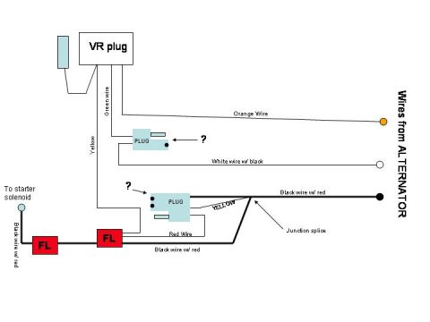
This is a color-coded wiring diagram for the Ford 2G alternator charging system, produced by RJM Injection Tech (copyright 2005). It shows the internal layout of the 2G alternator, including the stator, rectifier (spelled 'RECTFIER' in the diagram), and the internal regulator with its sensing and switching circuits and field winding, along with the regulator's A, S, and I terminals. Externally, the diagram traces the charging circuit: the alternator B+ output runs through a black/orange (B/O) wire and a 12-gauge fuse link to the battery positive terminal. A yellow/white (Y/W) sensing wire connects the fuse-link/battery junction to the regulator's A terminal, and a white/black (W/BK) stator wire feeds the S terminal. The regulator's I (indicator) terminal connects via a light green/red (LG/R) wire through a 20A 'Hot in Run' fused circuit, with an optional instrument cluster charge lamp shown in a dashed box, paralleled by a 510-ohm resistor. Readers can use this diagram to identify wire colors, terminal functions, and fuse/fuse-link locations when wiring, retrofitting, or troubleshooting a Ford 2G alternator installation.
Is this accurate? Sign in to help verify it.
Frequently asked questions
- What wire colors are used in the Ford 2G alternator wiring?
- The diagram shows B/O (black/orange) from the alternator B+ output, Y/W (yellow/white) to the regulator A terminal, W/BK (white/black) from the stator to the S terminal, and LG/R (light green/red) from the I terminal to the Hot-in-Run circuit.
- What fuse protects the 2G alternator's indicator circuit?
- The LG/R indicator wire runs to a 'Hot in Run' circuit protected by a 20A fuse.
- How is the 2G alternator output connected to the battery?
- The B+ output goes through a B/O wire and a 12-gauge fuse link on a red wire to the battery positive terminal.
- What is the resistor value across the charge lamp?
- A 510-ohm resistor is shown in parallel with the optional instrument cluster charge lamp.
- What terminals does the 2G regulator have?
- The internal regulator is shown with A, S, and I terminals: A receives the Y/W sensing wire, S receives the W/BK stator wire, and I connects via LG/R to the charge lamp/Hot-in-Run circuit.






No comments yet.