Home/
Registry/
Ford/
Taurus/
1992-1995/
1993 Ford Taurus/
Photo
supermotors.net/registry/media/576229
Ford Taurus / SHO ABS Module 55-Pin Connector Pinout - Circuits & Wire Colors

Reference · 1992-1995 TaurusAll 4 fuse & relay charts
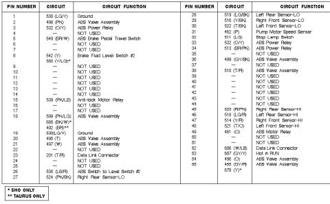

Pin assignment chart for the ABS control module listing pin numbers, circuit colors and circuit functions.
Part of 1992-1995 Ford Taurus Fuse & Relay Charts
This document is a 55-pin connector pinout chart for an anti-lock brake system (ABS) module, applicable to the Ford Taurus and Taurus SHO (per the footnotes '* SHO ONLY' and '** TAURUS ONLY'). For each pin number (1-55) it lists the circuit number, wire color code (e.g., 530 LG/Y, 498 PK, 549 BR/W), and circuit function. Functions covered include grounds (pins 1 and 19), ABS valve assembly circuits (pins 2, 18, 20, 21, 36, 38, 54, 55), ABS power relay (pins 3, 33, 34), ABS brake pedal travel switch (pin 5), brake fluid level switch #2 (pin 8), anti-lock motor relay (pin 15), data link connector (pins 23 and 52), pump motor speed sensor (pin 31), stop lamp switch (pin 32), ABS motor relay (pin 49), and Hot in RUN power (pin 53). All four wheel speed sensors are listed with HI and LO circuits: right rear (27/45), left rear (28/46), right front (29/47), and left front (30/48). Many pins are marked NOT USED. Several pins carry alternate circuits depending on model: SHO-only circuits 550 (Y/LG), 685 (BK/W), and 678 (Y), and Taurus-only circuit 492 (BR). Useful for ABS diagnostics, wiring tracing, and continuity testing at the ABS module connector.
Is this accurate? Sign in to help verify it.
Frequently asked questions
- Which pins are the wheel speed sensor circuits on this ABS connector?
- Right Rear: pin 27 (524 PK/BK, LO) and pin 45 (523 R/PK, HI). Left Rear: pin 28 (519 LG/BK, LO) and pin 46 (518 LG/R, HI). Right Front: pin 29 (516 Y/BK, LO) and pin 47 (514 Y/R, HI). Left Front: pin 30 (522 T/BK, LO) and pin 48 (521 T/O, HI).
- Which pins are grounds on this ABS connector?
- Pin 1 and pin 19 are both Ground, circuit 530 (LG/Y).
- Where do the data link connector circuits attach?
- Pin 23, circuit 201 (T/R), and pin 52, circuit 606 (W/LB), are Data Link Connector circuits.
- Which circuits differ between Taurus and SHO models?
- Circuits marked with * are SHO only: 550 (Y/LG) at pin 8, 685 (BK/W) at pin 18, and 678 (Y) at pin 55. Circuit 492 (BR) at pin 18 is marked ** Taurus only.
- Which pin provides switched power to the ABS module?
- Pin 53, circuit 687 (GY/Y), is labeled 'Hot in RUN'.





No comments yet.